The Primary motivation for raft foundations remains spreading all structural loads over a large base area in most instances the entire building footprints in order to reduce the contact bearing stress to acceptable limits.
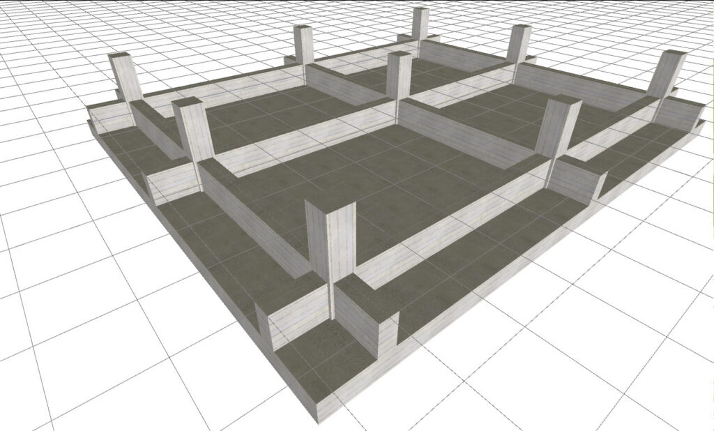
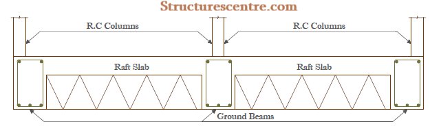
One of the most basic variants of the raft foundations is the beam strip raft. A beam strip raft utilizes a raft slab and ground bearing beams in two directions to support the heavy concentrated loads from the superstructure. The beams can be either designed to be up-standing or down-standing and are tied together by the raft slab which is sometimes supported on hardcore fillings or very compacted lateritic fillings (See figure 1).
Arguably, beam strip rafts with down-stand beams are the most popular form of raft foundation used in Nigeria. The basic advantage of this approach is that the raft slab performs it primary objective of spreading the load over a wide area, while also acting as the oversite concrete for the ground floor. However, there is a strong argument that this method is flawed for at least two reasons.
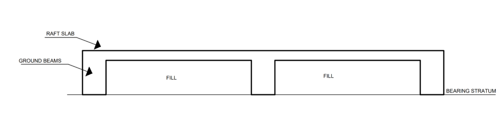
First, the reader should note that the assumption in the design of raft foundation assumes the raft slab is the principal structural element with the beams acting to stiffen the arrangement. This follows that the raft slab must be in contact with the bearing stratum. However, this is rarely the case, because a raft with down-stand beams sees the raft slab elevated above the bearing stratum (Figure 2). And since there is no evidence that the weight of the overburden is usually deducted to arrive at the recommended bearing capacity value, this constitutes a major challenge.
The challenge is complicated by the fact that the raft slab in most instances is certainly being constructed on a compacted fill. Aside from the naturally inherent problem of building on a fill, this negates the typical workflow of foundation design. To design a raft foundation, a bearing capacity value is required. But the bearing capacity of a fill can not be determined until the fill itself has been well compacted and a post compaction test carried out. Thus, this leaves a dead end because filling, in fact, can not commence until the ground beams are in place. And what we, in fact, know is that post compaction tests are rarely carried out in Nigeria.
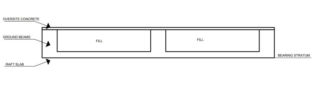
The most reliable method of designing beam strip rafts in this writer’s opinion is using the upstand beam. The advantage of having the raft serve the same purpose as the oversite concrete is lost, because a separate slab has to be constructed for the oversite concrete (see Figure 3). However, this approach allows the raft slab to sit on the bearing stratum, it is consistent with the design theory and assumptions and ensures that the raft foundation is designed correctly.
See: Cellular Raft Foundation | Worked Example
Worked Example
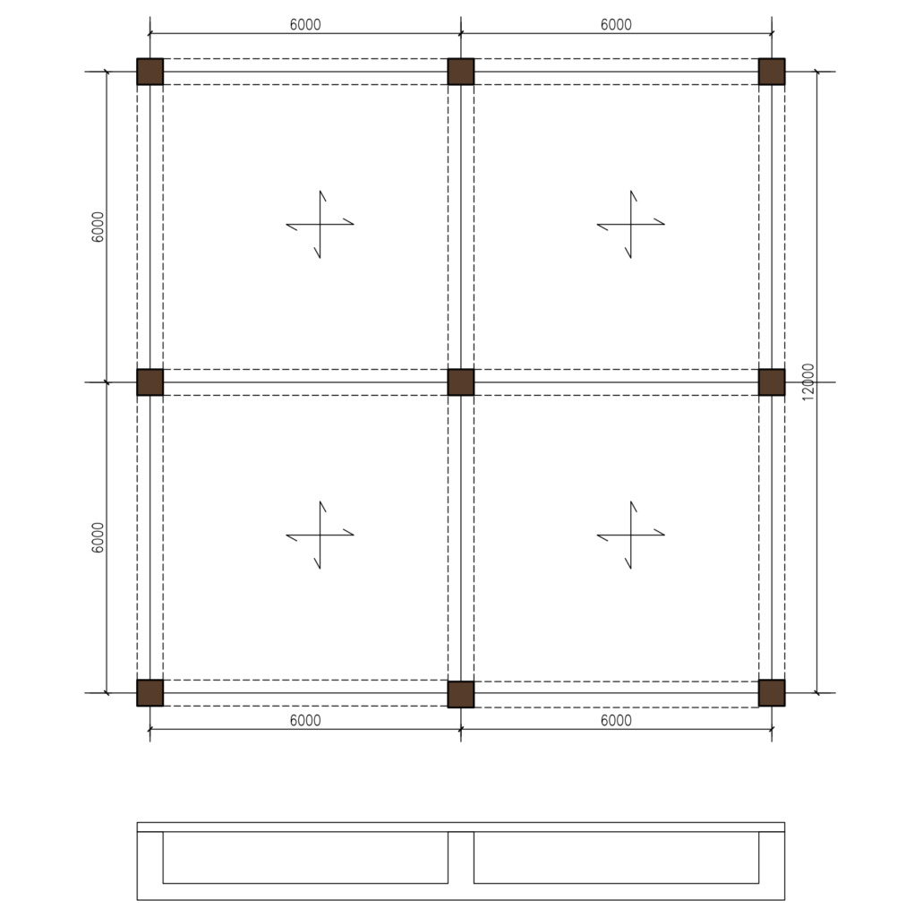
The figure shown below is the column loads at the base of proposed 3 a Storey concrete frame which is to be founded on a ground with poor bearing resistance. A beam strip raft with up-stand beams has been selected considering the geotechnical and structural factors. Carry out sufficient calculation using the data in table 1.0 to establish the sizes of the element and quantity of reinforcements required in the structural element.
- Bearing resistance = 45kN/m2
- Density of fill = 14.7kN/m3
- Concrete = C25/30
- Ground beams = 300mm x 1200mm
- Raft Slab = 200mm
| COLUMN | Gk | Qk |
| Side Column | 345 | 125 |
| Corner Column | 176 | 89 |
| Internal Column | 619 | 216 |
From inspection, the load is symmetrical about both axes of the building, therefore the point of application of the resultant will coincide with centroid of the base and since there are no eccentricities, for simplicity, the bearing pressure at the corners and anywhere in the raft will be assumed to be the same.
Serviceability Limit State
Permanent Actions
G_{k,cols} = 4\left( 176 \right) +4\left( 345 \right) +\left( 619 \right) \\=2703kNG_{k,slab}=0.2\times 12\times 12\times 25\\=720kNG_{k,soil}=1.0\times 11.1\times 11.1\times 14.7\\=1814.4kNG_{k}=G_{k,cols}+G_{k,slab}+G_{k,soil}\\=2703+720+1814.4=5237.4kNVariable Actions
Q_{k,col} =4\left( 89 \right) +4\left( 125 \right) +\left( 216 \right) \\ Q_{k}=1072kNTotal Actions @ SLS
N_{SLS} = G_{k}+Q_{k}=5237.4+1072\\=6309.4kNBearing Pressure Check
\sigma =\frac { N }{ A } \pm \frac { { M }_{ y } }{ { Z }_{ y } } \pm \frac { { M }_{ z } }{ { Z }_{ z } } =\frac { 6309.4 }{ \left( 12\times 12 \right) } =43.8kN/{ m }^{ 2 }\left( \sigma =43.8kN/{ m }^{ 2 } \right) <\left( { p }_{ T }=45kN/{ m }^{ 2 } \right)Ultimate Limit State
Total Actions @ ULS
N_{k} =\left( 1.35( 2703+1814.4 \right) +\left( 1.5\times 1072 \right)\\ =7706.5kNBearing pressure @ULS
{ \quad \sigma }_{ max }=\frac { N }{ A } \pm \frac { { M }_{ y } }{ { Z }_{ y } } \pm \frac { { M }_{ z } }{ { Z }_{ z } } =\frac { 7706.5 }{ (12\times 12) } =53.5kN/{ m }^{ 2 }Raft Slab Design
Having determined the pressure at the ultimate limit state, the raft slab is designed as a two-way spanning slab for this pressure (53.5kN/m2) in accordance with code provisions. Note that in this case, the load acts upwards, hence the tensile reinforcement required in the span would be positioned at the top while those required at the supports are fixed at the bottom.
=\frac {l_{y}}{ l_{x} } =\frac{6}{6}=1Utilizing coefficients from table for two ways slabs (two adjacent sides discontinuous), the magnitude of the moment in the slabs can be determined.
C𝑜𝑒𝑓𝑓𝑖𝑐𝑖𝑒𝑛𝑡𝑠 = −0.047 & 0.036
Flexural Design
Negative Moment @ Supports
M_{Ed}=-0.047\times53.5\times 6^2=90.5kN.m/mAssuming cover to reinforcement of 50mm, 16mm bars
d=h-(c+\phi/2)\\=200-(30+16/2)=162mm
k=\frac{M_{Ed}}{bd^{2}f_{ck}}=\frac{90.5\times10^{6}}{10^{3}\times162^{2}\times 25}=0.138z=0.86d=0.86\times =139.3mm
A_{s}=\frac{M_{Ed}}{0.87f_{y}z}=\frac{90.5\times10{^6}}{0.87\times 410\times139.3}=1821.4mm^{2}/mUse T16mm bars @ 100mm Centers Bottom (As, prov = 2010mm2) Both ways
Positive Moment in Spans
M_{Ed}=0.036\times53.5\times 6^2=69.3kN.m/mAssuming cover to reinforcement of 50mm, 16mm bars
d=h-(c+\phi/2)\\=200-(30+16/2)=162mm
k=\frac{M_{Ed}}{bd^{2}f_{ck}}=\frac{69.3\times10^{6}}{10^{3}\times162^{2}\times 25}=0.106z=0.9d=0.9\times162 =145.8mm
A_{s}=\frac{M_{Ed}}{0.87f_{y}z}=\frac{69.3\times10{^6}}{0.87\times 410\times145.8}=1332.5mm^{2}/mUse T16mm bars @ 150mm Centers Bottom (As, prov = 1340mm2) Both ways
Ground Beam Design
The beams designed for the applied pressure, transferred from the raft slab to the beams.
Action on Beam
w_{x,beam}=2\times\frac{{\sigma }_{ max }l_{x}}{3}= 2\times\frac{53.5\times6}{3}=214kN/mAnalysis
Since the geometry of the beam is equal and the actions on the beams are uniform, simple coefficient can be used to obtain the flexural moments and shear forces in the beam.
Flexural Design
Supports
M_{Ed}=0.11\times214\times 6^2=847.4kN.mAssuming cover to reinforcement of 50mm, 20mm bars and 10mm links
d=1200-(c+\phi/2+links) \\=1200-(50+20/2+10) =1130mm
b_{eff}= b_{w} = 300mmk=\frac{M_{Ed}}{bd^{2}f_{ck}}=\frac{847.4\times10^{6}}{300\times1130^{2}\times 25}=0.088z=0.91d=0.91\times1130 =1028mm
A_{s}=\frac{M_{Ed}}{0.87f_{y}z}=\frac{847.4\times10{^6}}{0.87\times 410\times1028}=2311mm^{2}Use 8T20mm bars @ Bottom (As, prov = 2512mm2)
Spans
M_{Ed}=0.09\times214\times 6^2=693.4kN.mAssuming cover to reinforcement of 50mm, 20mm bars and 10mm links
d=1200-(c+\phi/2+links) \\=1200-(50+20/2+10) =1130mm
b_{eff}= b_{w} = 300mmk=\frac{M_{Ed}}{bd^{2}f_{ck}}=\frac{693.4\times10^{6}}{10^{3}\times1130^{2}\times 25}=0.022z=0.95d=0.95\times1130 =1073mm
A_{s}=\frac{M_{Ed}}{0.87f_{y}z}=\frac{693.4\times10{^6}}{0.87\times 410\times1073}=1812mm^{2}Use 6T20mm bars @ Top (As, prov = 1884mm2)
Shear Design
V_{Ed}=0.6w_{s,beam}l=0.6\times214\times6\\=770.4kNBy inspection, the shear force is small, hence shear reinforcement will be provided based on the minimum requirement.
\frac{A_{sv,min}}{s_{v}}=\frac{0.08f_{ck}^{1/2}b_{w}}{0.87f_{y}}=\frac{0.08\times 20^{1/2}\times 300}{0.87\times 410}=0.33s_{v} =0.75d =0.75\times 1130 =847.5mmUse T10mm bars @ 200 centers (0.78)
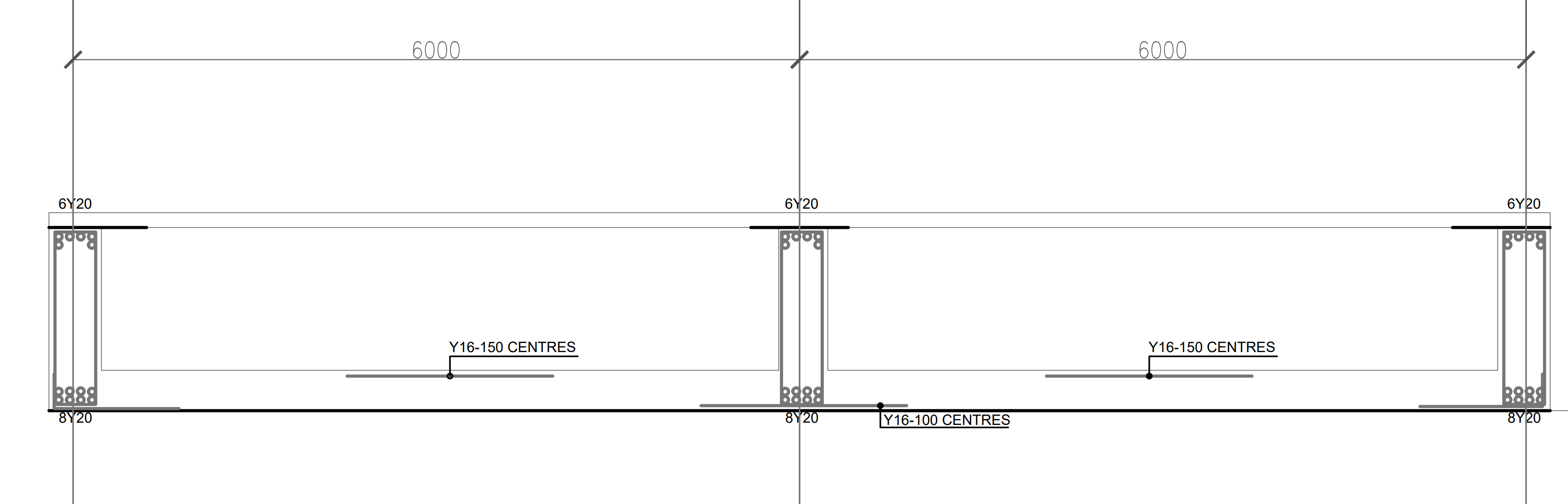
Figure 5: Design resume
Detailing Considerations
The area of steel provided in the raft slab and ground beam is subject to minimum steel areas required and detailing rules. For the ground beams, the advice given in Eurocode 2 for the side faces of deep beams holds. The UK National Annex recommends that 0.2% is provided in each face. The distance between bars should not exceed the lesser of twice the beam depth or 300 mm.