This article presents the design of cellular raft foundation, a spread foundation arrangement with two way interlocking ground beams with a ground bearing slab in contact with the soil and a suspended slab at the top surface
Introduction
Raft foundations belongs to the family of spread foundations – foundations that are cited on a shallow bearing stratum. They are necessitated by poor underlying stratum, or where the required depth to a suitable bearing stratum is excessive, where the load carrying capacity of the underlying soil strata deteriorates with depth or even where the loads from a superstructure is enormous relative to the capacity of the soil. Rafts are employed to spread the applied loads over a large base area, at least the building footprint, thereby reducing the contact bearing stress to acceptable limits.
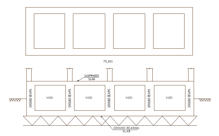
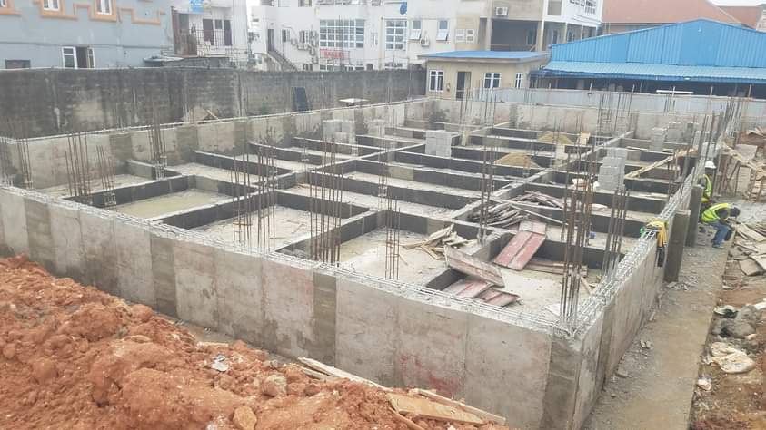
There are several types of raft foundation, this has been fully appraised in a previous post, (See: Foundation Types: Selection Criteria). However, the focus of this post is on the cellular raft foundation (Figure 1) which offers extra advantage when compared to the slab rafts or beam strip rafts. First, they are very suitable where very heavy concentrated forces are to be sustained on relatively weaker soils. Secondly, the removal of the overburden as a result of the hole created by the cellular invariably leads to an increase in bearing capacity. Notwithstanding, the cellular spaces created also offers the advantage for use as living spaces, storage and for service installations.
A typical cellular raft foundation consists of a series of deep reinforced concrete beams connecting a suspended slab with the bearing slab. The suspended slab can be equated with the ground floor slab in a typical structure, but in this case completely suspended from the ground, while the bearing slab below the suspended slab makes the contact with ground.
Preliminary Sizing & Considerations
Having selected a cellular raft as a viable structural solution, at the preliminary design stage, the designer of a cellular raft must decide on the depth required. This depends on the depth of overburden required to be removed and the required flexural moment capacity of the cellular form. It is very common for the raft depth to be dictated by the estimated flexural moment to be induced, with the reduced overburden load being a bonus. For example, a building with span restrictions in any directions could lead to large shear forces and flexural moments thus, requiring very deep beams.
The design of a raft foundations can be sometimes complicated especially for beam strip rafts or cellular rafts. The designer must make a judicious choice between the flexible approach or the conventional rigid base method.
In the flexible approach, the raft is flexible relative to the supporting soil, the contact pressure is anything but uniform and the deflection of the raft slab will vary with location. This can be idealized using the beam on elastic foundation theory. The rigid method on the flip side assumes that the raft is stiff relative to the soil, hence the raft is idealized as fully rigid member without any consideration of the elastic properties of the soil and its interaction with the structure. In theory, either of the flexible or rigid approach can be used to design a raft, however, in reality no raft is wholly flexible nor is it totally rigid, these are merely reasonable assumptions that lies completely within the remit of the designer.
The flexible approach would normally yield lower design values than the rigid method, but is only suitable with finite element powered software packages, while the rigid would otherwise give higher design values and it’s practically suitable for hand calculations.
Design Principle
As stated in the preceding section, the conventional rigid approach treats the raft as a member that is rigid relative to the soil without recourse to the elastic properties of the soil. The designer must start with estimating the design column loads and relating this to the overall plan of the building and ground pressures. The calculation for the ground pressure will be based on the center of gravity of the loads while considering the relative stiffness of the raft itself.
The entire raft is divided into an idealized large beam member in both directions, and the row of column loads normal to the direction of the beam is summed up. With this column load applied on the idealized beam member, the eccentricities of the resultant loads from the centroid of the raft can be found and used to determine the ground pressures at the corners of the building (Figure 2). Assume N is the total axial action; A is the area covered by the raft; ey and ez are the eccentricities; My and Mz are the induced moment in both direction due to eccentricities and Zy and Zz are the section modulus assuming a symmetrical plan. The ground pressure in each corner of the building can be estimated from the equation:
\sigma =\frac { N }{ A } \pm \frac { { M }_{ y } }{ { Z }_{ y } } \pm \frac { { M }_{ z } }{ { Z }_{ z } } Where: My =N × ey & Mz=N × ez
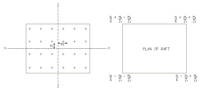
Again, these theoretical pressures do not reflect the reality and would not necessarily be achieved on site. A difficulty arises when the designer tries to assess the actual ground pressures. These pressures would depend on the sub-strata the flexibility of the raft and the loads occurring at any given time at which these pressures are being determined.
None of these can be estimated accurately and it’s not necessary to do so. The true design of a raft is somewhere between the flexibility and rigid methods.
Elements Design
The cellular rafts technically consist of three elements, the suspended slab, the bearing slab and the adjoining beams. The upper slab is designed as a purely suspended slab subjected to the design actions at ground floor level. The load on the ground floor is then added to the loads coming from other parts of superstructure and taken down to the slab below to determine the contact pressure at ultimate limit state. This contact pressure is used to design the lower slab by considering it as an inverted suspended slab. The actions applied on the lower slab is then distributed amongst beams and used for the beam design.
Worked Example
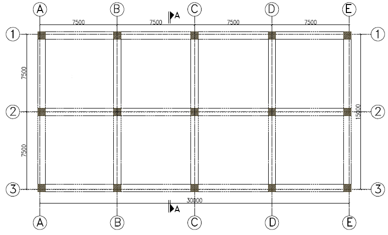
The plan shown in figure 3 is the column loads at the base of 8 a storey concrete frame which is to be founded on a ground where future mining activity is to be anticipated. In other to deal with the future likely subsidence wave, a cellular raft has been selected as a very viable solution considering the geotechnical and structural factors. The soil investigation report has indicated that a net allowable bearing pressure of pa = 75kN/m2 is required to keep differential settlement in check. Carry out sufficient calculation to establish the sizes of the element and quantity of reinforcements required.
Presumed bearing resistance =75kN/m2
Soil Unit weight = 20 kN/m3
Imposed load (ground floor) = 5kN/m2
Concrete C30/37; Fy = 460Mpa
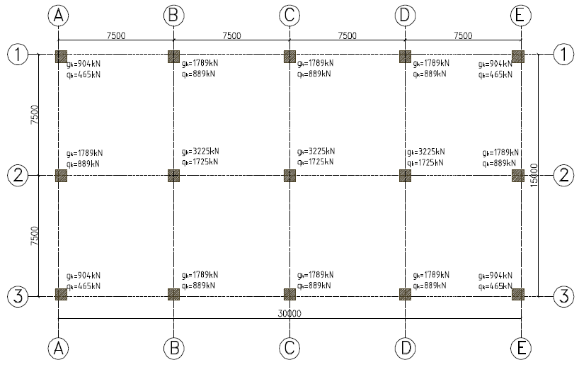
By inspection, the load is symmetrical about both axes of the building, hence the point of application of the resultant will coincide with centroid of the base and thus, there are no eccentricities and the bearing pressure at the corners and anywhere in the raft will be the same.
Serviceability Limit State
Actions
Superstructure loads
Permanent Actions
G_{k,s} = 4\left( 904 \right) +8\left( 1789 \right) +3\left( 3225 \right) \\=27603kNVariable Actions
Q_{k.s} =4\left( 465 \right) +8\left( 889 \right) +3\left( 1725 \right) \\=14147kNN_{s} =27603+14147= 41750kNFoundation loads
Permanent actions
upper slab
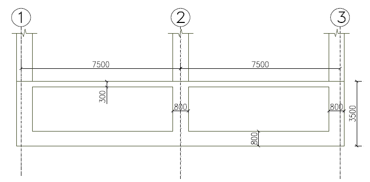
=0.3\times 15\times 30\times 25=3375kN
lower slab
=0.8\times 15\times 30\times 25=9000kN
beam webs
=0.8\times 2.4\times 165\times 25=7920kN
G_{k,f}=3375+9000+7920\quad \\ =20295kNVariable Actions
Imposed loading
Q_{k,f}= 15\times 30\times 5=2250kNN_{f}=20295+2250=22545kNTotal loads @ SLS
N =41750+22545=64295kN
Bearing Pressure Check
\sigma =\frac { N }{ A } \pm \frac { { M }_{ y } }{ { Z }_{ y } } \pm \frac { { M }_{ z } }{ { Z }_{ z } } =\frac { 64295 }{ \left( 15\times 30 \right) } =142.8kN/{ m }^{ 2 }If the net pressure at the formation level of 3.5m is, pa = 75kN/m2, the excess overburden pressure is given as:
{ p }_{ o }=20\times 3.5=70kN/{ m }^{ 2 }{ p }_{ T }={ p }_{ a }+{ p }_{ o }=75+70=145kN/{ m }^{ 2 }\left( \sigma =142.8kN/{ m }^{ 2 } \right) <\left( { p }_{ T }=145kN/{ m }^{ 2 } \right)Ultimate Limit State
Actions
Superstructure loads
N_{k,s} =\left( 1.35\times 27603 \right) +\left( 1.5\times 14147 \right) \\ =58484.6kNFoundation loads
N_{k,f} =1.35\left( 3375+7920 \right) +\left( 1.5\times 2250 \right) \\ =18623.25kNTotal loads @ ULS
N =58484.6+18623.25\\ =77107.85kN
Bearing pressure
{ \quad \sigma }_{ max }=\frac { N }{ A } \pm \frac { { M }_{ y } }{ { Z }_{ y } } \pm \frac { { M }_{ z } }{ { Z }_{ z } } =\frac { 77107.85 }{ (15\times 30) } =171.35kN/{ m }^{ 2 }Designing the Bottom Slab
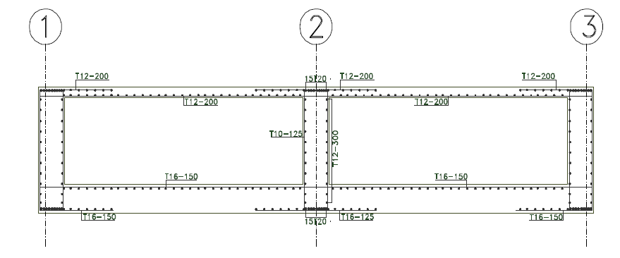
Having determined the pressure at the ultimate limit state, the bottom slab is designed as a two-way spanning slab for this pressure (171.35kN/m2) in accordance with code provisions. It should be noted that in this case, the load is acting upwards, hence the tensile reinforcement required in the span would be positioned at the top while those required at the supports are fixed at the bottom.
Designing the Top Slab
The top slab is designed as any other suspended slab in the superstructure – designed as two-way spanning slab for the applied permanent and variable actions.
Designing the Beam
The beams are considered as I concrete sections and are designed for actions transferred from the bottom slab to the beams. Under normal conditions, the depth of beam involved would mostly be conservative relative to the span, hence the corresponding reinforcement would be light.
To view the Full article in pdf, click here
Thank you and please share this post.
Thanks for this explanation. I would like to ask, what text book can one get further information on cellular rate design. Also what software acn one use to achieve its design.