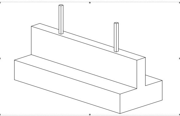
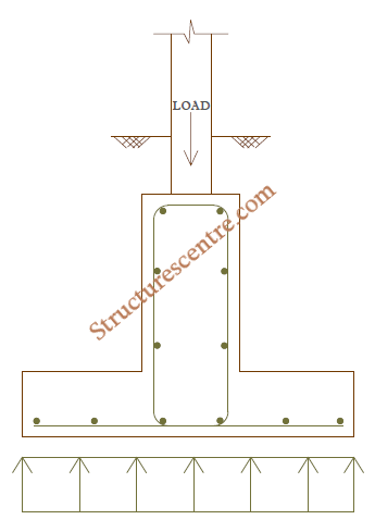
The inverted T-beam foundation derives its name from its cross-sectional shape which resembles an inverted letter “T”. It is a combination of an upstand ground beam and a concrete slab (Figure 1). The horizontal slab which is analogous to a pad representing the top of the inverted T and the other part being the upstand beam. The motivation for an inverted T beam foundation usually results from the need to deliver the design actions from two or more heavily loaded columns sharing a single pad base safely to the ground, either due to overlapping single bases or site constraints.
In many combined footings – especially those required to transmit very high axial forces and with moderately spaced columns, longitudinal hogging moment are a major problem, hence the upstanding ground beam provided ensures a stiffer cross-section towards resisting the highly induced bending moment and shear forces in the longitudinal direction. They are also used in areas of mining activity, where bending from differential subsidence movement is critical but where tensile and compressive ground strains in the foundation can be controlled. Generally, the decision to design an inverted T-beam usually follows the need to:
- Combine bases that would otherwise tend to overlap
- Design a combined footing for a distantly spaced, heavily loaded columns
- Ease construction through the use of a continuous strip rather than isolated pads where they are becoming closely spaced
- Reduce differential settlement
Sizing the Design
Having selected the inverted T – beam as a viable structural solution for a foundation problem, the designer must now decide on the sizes of the structural elements that make up the foundation. An inverted T -beam foundation consist of practically two elements; the upstand beam and the slab (flange). As stated in the preceding section, the motivation for embedding a beam into the combined base arrangement is to enable it resist high longitudinal stresses. Hence deciding on the size of the upstand beam will depend on the magnitude of the induced bending moment and shear forces in the longitudinal direction.
The size of the beam can be obtained from preliminary sizing rules. For relatively loaded foundation, the beam depth is typically within the range of (900-2500mm), while the width of the beam is sized equal to the cross-section of the columns being supported, or increased moderately as the need may be, if there is a problem with accommodating the reinforcement provided. The slab (flange) thickness is determined on the basis of the contact pressure acting on the cantilever and the magnitude of the induced bending moment and shear forces in the transverse direction.
Design Procedures
Generally, the design procedure for an inverted T-beams would follow the same approach as any combined or balanced base:
- Assume a trial size for the beam and slab
- Determine the required size of the footing using the soil bearing resistance and the loads at serviceability limit state
- Proportion the footing for uniform pressure distribution by finding the location of the centroid and adjusting the footing appropriately
- Determine the bearing pressures at ultimate limit state
- Calculate the bending moment and shear forces in the longitudinal and transverse direction
- Design the flexural reinforcement in the longitudinal direction using the beam effective depth
- Design the flexural reinforcement in the transverse direction using the slab effective depth
- Verify shear at critical positions
- Verify detailing requirement
Worked Example
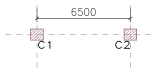
A combined footing is required for two heavily loaded columns in a proposed commercial building. Using the Design data provided in Table 1 and Figure 2. Design an inverted T-beam footing assuming a presumed bearing resistance of 300kN/m2 using C25/30 concrete with 460Mpa bars
| Column | Sizes | Gk(kN) | Qk(kN) |
| C1 | (500x500) | 1945 | 817 |
| C2 | (500x500) | 1945 | 817 |
Serviceability Limit State
We start, by determining the design actions at the serviceability limit state
{ N }_{ Ed,C1 }={ 1.0G }_{ k }+{ 1.0Q }_{ k }\\=1945+817=2762kN{ N }_{ Ed,C2 }={ 1.0G }_{ k }+{ 1.0Q }_{ k }\\=1945+817=2762kNAssume the self-weight of the foundation is 15% of the total axial loads at serviceability
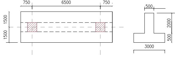
{ N }_{ Ed }=(1+0.15)\times (2762+2762)\\=6352.6kN{ A }_{ req }=\frac { { N }_{ Ed} }{ { p }_{ s } }= \frac { { 6352.6 } }{ 300 }=21.17{ m }^{ 2 }Assume a rectangular base of (8m x 3m) = Apro = 24m2
Since the columns are symmetrically loaded, it therefore follows that the resultant of the column loads will coincide with the centroid of the footing, hence the foundation layout is as shown in Figure 3.
Ultimate Limit State
{ N }_{ Ed,C1 }={ 1.35G }_{ k }+{ 1.5Q }_{ k }=3851.25kN{ N }_{ Ed,C2 }={ 1.35G }_{ k }+{ 1.5Q }_{ k }=3851.25kN{ p }_{ u }=\frac { { N }_{ Ed,C1 }+{ N }_{ Ed,C2 } }{ { A }_{ pro } }=\frac { 3851.25+3851.25 }{ 24 } =321kN/{ m }^{ 2 }Analysis
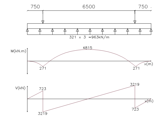
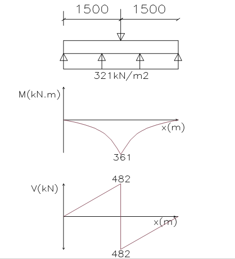
The footing is idealized as an inverted flanged beam with supports at the column centerlines and subjected to the earth pressure, in this case (321kN/m2). The Analysis is carried out in the longitudinal direction and transverse direction and the resulting moment and shear force diagrams are presented below as Figure 4 & 5.
Analysis in Longitudinal Direction
Analysis in Transverse Direction
Flexural Design (Longitudinal Direction)
Hogging in Span
{ M }_{ Ed }=4815kN.mAssuming cover to reinforcement of 50mm, 25mm tensile bars, 16mm compression bars & 8mm links
{ d }^{ ' }=\left( { c }_{ nom }+links+\phi /2 \right) \\=50+10+16/2=68mm{ d }=h-\left( { c }_{ nom }+links+\phi /2+\phi \right)=2500-\left( 50+10+25/2+25 \right) =2402mm
b={ b }_{ eff }=3000mm k=\frac { { M }_{ Ed } }{ b{ d }^{ 2 }{ f }_{ ck } } =\frac { 4815\times { 10 }^{ 6 } }{ 3000\times { 2402 }^{ 2 }\times 25 } =0.011z=\quad 0.95d\quad =0.95\times 2402\quad =2282mm
{ A }_{ s,req }=\frac { { M }_{ Ed } }{ 0.87{ f }_{ yk }z } =\frac { 4815\times { 10 }^{ 6 } }{ 0.87\times 460\times 2282 } \\=5272.3{ mm }^{ 2 }Try 11T25mm bars Top (Two Layers) (As, prov = 5401mm2)
Sagging in Supports
{ M }_{ Ed }=271kN.mAssuming cover to reinforcement of 50mm, 16mm tensile bars, 16mm compression bars & 8mm links
{ d }^{ ' }=\left( { c }_{ nom }+links+\phi /2 \right) \\=50+10+16/2=68mm{ d }=h-\left( { c }_{ nom }+links+\phi /2 \right)=2500-\left( 50+10+16/2 \right) =2432mm
b={ b }_{ w }=500mm k=\frac { { M }_{ Ed } }{ b{ d }^{ 2 }{ f }_{ ck } } =\frac { 271\times { 10 }^{ 6 } }{ 500\times { 2432 }^{ 2 }\times 25 } =0.0037z=\quad 0.95d\quad =0.95\times 2432\quad =2310.4mm
{ A }_{ s,req }=\frac { { M }_{ Ed } }{ 0.87{ f }_{ yk }z } =\frac { 271\times { 10 }^{ 6 } }{ 0.87\times 460\times 2310.4 } \\=293.09{ mm }^{ 2 }Try 10T16mm bars Bttm (As, prov = 2010mm2)
Flexural Design (Transverse Direction)
Sagging in Supports: At the column face
{ M }_{ Ed }=251kN.m/mAssuming cover to reinforcement of 50mm, 25mm tensile bars, 16mm compression bars & 8mm links
{ d }=h-\left( +links+\phi /2 \right) \\ =500-\left( 50+16/2 \right) =442mmb=1000mm
k=\frac { { M }_{ Ed } }{ b{ d }^{ 2 }{ f }_{ ck } } =\frac { 251\times { 10 }^{ 6 } }{ 1000\times { 442 }^{ 2 }\times 25 } =0.05z=\quad 0.95d\quad =0.95\times 442\quad =419.9mm
{ A }_{ s,req }=\frac { { M }_{ Ed } }{ 0.87{ f }_{ yk }z } =\frac { 251\times { 10 }^{ 6 } }{ 0.87\times 460\times 419.9 } \\=1493.6{ mm }^{ 2 }Try T16mm – 125mm bars Bttm (As, prov = 1608mm2)
Shear Design (Longitudinal Direction)
{ V }_{ Ed }=\quad 3219kNBy inspection, shear reinforcement is required, hence:
\theta =0.5{ sin }^{ -1 }\left( \frac { { 5.56V }_{ Ed } }{ { b }_{ w }d\left( 1-{ f }_{ ck }/250 \right) { f }_{ ck } } \right)=0.5{ sin }^{ -1 }\left( \frac { 5.56\times 3219\times { 10 }^{ 3 } }{ 500\times 2402\left( 1-25/250 \right) 25 } \right) \\=20.7cot\theta =2.65>\quad 2.5\quad ;\quad take\quad cot\theta =2.5
\frac { { A }_{ sv } }{ { s }_{ v } } \ge \frac { { V }_{ Ed } }{ zcot\theta { f }_{ wd } }=\frac { 3219\times { 10 }^{ 3 } }{ \left( 0.9\times 2402\times 2.5 \right) \times 460 } =1.29max\quad spacing\quad =0.75d=1801.5mm
\frac { { A }_{ sw,min } }{ { S }_{ v } } =0.08\frac { \sqrt { { f }_{ ck } } }{ { f }_{ yk } } { b }_{ w }=0.43Use 3T10mm – 150mm centers (1.57)
Shear Design (Transverse Direction)
The critical section for shear is taken at d from the face of the column
{ V }_{ Ed }=482-\left( 0.25+0.442 \right) 321=260kN\theta =0.5{ sin }^{ -1 }\left( \frac { { 5.56V }_{ Ed } }{ { b }_{ w }d\left( 1-{ f }_{ ck }/250 \right) { f }_{ ck } } \right)=0.5{ sin }^{ -1 }\left( \frac { 5.56\times 260\times { 10 }^{ 3 } }{ 1000\times 442\left( 1-25/250 \right) 25 } \right) \\=4.42cot\theta =13.7>\quad 2.5\quad ;\quad take\quad cot\theta =2.5
\frac { { A }_{ sv } }{ { s }_{ v } } \ge \frac { { V }_{ Ed } }{ zcot\theta { f }_{ wd } }=\frac { 260\times { 10 }^{ 3 } }{ \left( 0.9\times 442\times 2.5 \right) \times 460 } =0.57max\quad spacing\quad =0.75d=298.35mm
\frac { { A }_{ sw,min } }{ { S }_{ v } } =0.08\frac { \sqrt { { f }_{ ck } } }{ { f }_{ yk } } { b }_{ w }=0.87Use 6T8mm – 275mm centers (1.1)
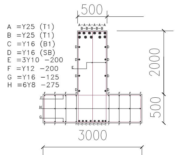
Detailing checks should be carried out to ensure compliance with code specification. Figure 6 Shows a section through the foundation. During construction, concreting is carried out in two phases, with the ground slab being cast up to the top of the flange leaving a roughened surface with the stirrups of the beam projecting outwards. After which the formwork for the main beam is then put in place and cast up to the top surface.
Also See: Designing a Combined Footing-Worked Example
Thank You!