Piling is one of the oldest types of foundation technique known to mankind. Its principle is based on transferring the loads from a structure through strata of low bearing capacity to deeper soil strata having higher bearing capacity, or directly on a rock. When piling is employed for foundation, the loads from the structure are either transferred to the underlying soil either by end-bearing or friction or a mixture of both depending on the soil conditions and the magnitude of the loads been envisaged from the super-structure.
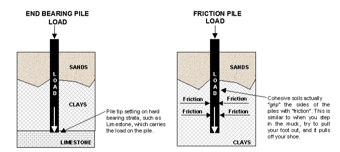
End-bearing piles transfer their load on to a firm stratum located at a considerable depth below the base of the structure and they derive most of their carrying capacity from the penetration resistance of the soil at the toe of the pile while friction piles transmit most of their load to the soil through skin friction between the pile itself and the soil strata (Figure 1).
There are several types of piles that all follow the same principle. They can be made from a variety of materials including timber, steel and reinforced concrete; the last being the most common.
Types of Piling
Piling methods can be placed into two categories: displacement and replacement.
Displacement piles – shift soil away from the pile itself and their installation typically generates significant noise and vibration. The exceptions to this are displacement augers and bottom driven steel tubes.
Replacement piles – extract the soil to form a shaft, which is then filled with a material that creates the pile. This method of piling does not generate as much noise or vibration.
Generally speaking, piling can appear in the following forms:
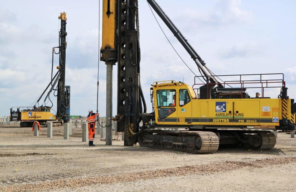
Driven Piles: Driven piles are considered to be displacement piles. A pre-assembled pile is driven into the soil. The pile is made up of sections and is linked together via couplings (See Video 1).
Bored Piles: Bored piles (Replacement piles) are generally considered to be non-displacement piles a void is formed by boring or excavation before piles is produced by pouring in concrete into the void (See Video 2)
Jack Piles: Piles that are pressed into the soil via a jack.
Selecting a Pile Type
The selection of a pile type will depend on certain factors, these are;
- Load envisaged from the super-structure
- Soil conditions (both geotechnical and environmental)
- Site access
- Construction Programme
- Site Constraints (e.g. availability of space)
For example, a 5 Storey building in a residential area that is to be built on a clay soil with layers of silt in it will likely have concrete piles placed via a bored process. This reduces the risk of piles failing as the soil collapses into the dug shaft, as a result of the concrete being installed while the pile shaft is excavated. This method does not generate much in the way of noise or vibration either, which is important for a site located within a residential area.
Design Responsibility
The pile design responsibility can fall into either the designer of the structure’s remit or to a specialist contractor. In the case of the former, all of the design information is fed directly to the specialist contractor who does not take on any of the design responsibility of the piles.
The other scenario places the responsibility for designing the piles on the specialist contractor, and the amount of information provided by the designer will vary in terms of comprehensiveness.
In some instances, a pile layout along with loads to each pile is defined and a limit on settlement provided. At other times it is only the loads from the superstructure that are explained, and it is up to the specialist contractor to develop the layout of the piles and their loading. In both cases, the loads specified must be both un-factored and permanent in nature.
This latter approach places a great deal of design responsibility onto the specialist contractor, but it does afford them the opportunity to exercise skills and expertise that the designer of the super-structure is unlikely to have. This can in theory lead to more economical designs over those of a designer, with less of a focus on substructure design, which would typically be the responsibility of the engineer overseeing the super-structure.
Pile Testing
Clause 7.5 in BS EN 1997-1 defines which pile load tests need to be carried out on all forms of piling. Specifically, pile tests need to be carried out when the following conditions arise:
- Where the piles have not been tested in similar soil and loading conditions
- When piles are subjected to loading, that theory and experience do not give confidence in the pile design. Load testing will simulate the design loading condition.
- During installation, the behaviour of the piles is different from what was expected, i.e. from the assumptions made from the soil property data gleaned from the earlier site investigations
- A method of pile installation and/or type of pile is being used where there is no experience of it being employed
In addition to mandatory testing, specific tests may form part of the pile design and installation process. Testing can inform the suitability of the chosen pile type, how the soil is interacting with the pile and the overall design of the sub-structure.
The extent of testing does have an impact on the design factor of safety of the piles. If a significant amount of testing is to be carried out during construction, then the factor of safety can be reduced, while the opposite is also true.
There are two forms of testing: Load and Integrity.
Load Tests
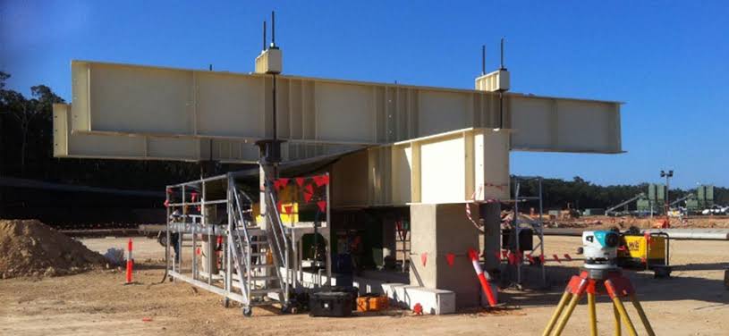
With respect to load testing, piles that are primarily subjected to axial compressive loads can be tested via two methods. One is the constant rate penetration test (CRP). This sees a force placed upon the pile that is slowly increased until the pile fails as it penetrates the soil. The other method is the maintained load (ML) test. This has a pile loaded to up to twice the design load and a time vs. settlement chart is plotted every time the load is applied to the test pile and removed.
CRP testing is destructive and is therefore reserved for piles that are installed for that purpose only. ML testing
Integrity Tests
Integrity tests are typically not destructive and set out to determine the overall quality of the pile along its length. Six of the most commonly used testing methods are summarized here:
Acoustic test – A tube (or sometimes a pair of tubes) is cast into the pile and the integrity checked using a sonde, which has an acoustic transmitter and receiver at both ends. This is dropped into the hole(s), which is fi
Stress wave test – This testing method is based on a dynamic pulse that is emitted through the pile via a repeatedly dropped mass applied to the top of
Electrical test – These tests measure the electric potential within the pile and the soil it is inserted into. The results from these measurements are then used to determine the integrity of the pile.
Dynamic response test – This testing method subjects the pile to a continuous stream of vibrations across a broad set of bandwidths. The method by which the integrity of the pile is determined is somewhat similar to seismic test methods, although the magnitude of the force being applied to the pile is much less.
Seismic test – This is based on measuring the
Radiometric test – This test detects flaws in the pile by measuring the radiation within it. Like acoustic tests, a tube is cast into the pile and a sensor is placed within the tube. Rather than sound, radiation is measured which is used to determine the integrity of the pile.
See: Geotechnical Design of Concrete Piles to EC7
Citation & Sources References
Fleming K. et al. (2008) Pile Engineering 3rd ed. Oxford, UK: Taylor and Francis Group
Tomlinson M. and Woodward J. (2007) Pile Design and Construction Practice 5th ed. Oxford, UK: Taylor and Francis Group
Excuse for that I interfere … To me this situation is familiar. I invite to discussion.
can you buy tadalafil over the counter – buy cialis generic tadalafil for sale cheap
how to order cialis online safely – buy cialis cialis 5mg online pharmacy
how to order viagra in canada – how much is viagra cost sildenafil tablet 50mg
online viagra best – viagra online cheap viagra 25mg price in india
cialis generic online pharmacy – cialis brand discount generic cialis canada
cialis in canada over the counter – online canadian pharmacy generic cialis usa pharmacy
ivermectin where to buy for humans – ivermectin 1%cream stromectol 6mg
ivermectin 4 tablets price – ivermectin oral solution ivermectin for sale
online casino games for real money – real money casino online usa slot machines
casino online real money – best real casino online online casino real money no deposit
ed pills walmart – buy ed pills with paypal dr oz ed pills free trial
best otc ed pills – best ed pills pills erectile dysfunction
buy cheap prednisone online – buy 40 mg prednisone 20mg prednisone
deltasone 20 mg price – compare prednisone prices order prednisone
ivermectin for humans – stromectol tablet price ivermectin ireland
ivermectin 12 mg – buy ivermectin nz ivermectin for sale online
medications that cause erectile dysfunction – natural treatment for ed ed treatment drugs
Дом Гуччи смотреть фильм онлайн
pills for ed – canadian online pharmacy what is the most effective pill for ed
ventolin price usa – albuterol sulfate inhaler buy ventolin
ventolin nebules – ventolin inhaler ventolin inhaler
buy misoprostol 200mcg – cytotec price canada cytotec pills for sale in south africa
cytotec 200 mcg price – generic cytotec 200 mcg cytotec 25 mg
how much is doxycycline 100mg – doxycycline 100mg tablets for sale can i buy doxycycline over the counter uk
how can i get doxycycline over the counter – doxycycline 100mg capsules buy doxycycline 40 mg generic
neurontin tablets uk – medication neurontin 300 mg synthroid 25 mg cost
neurontin price in india – online synthroid prescription synthroid 100 mg
Cialis 5 Vidal
female viagra south africa – sildenafil price uk
viagra online without prescription – generic viagra online purchase in usa
female cialis canada – cialis soft tabs canada buy cialis from india online
cialis price australia – order cialis pills buy tadalafil no prescription
finasteride on sale no prescription
Pharmacie Viagra Cialis
vardenafil for sale online – vardenafil 10mg order generic vardenafil online
generic vardenafil 20 mg – cialis vardenafil online generic vardenafil 10mg
в хорошем качестве
http://buysildenshop.com/ – citalopram viagra
stromectol 3 mg – stromectol sales ivermectin 0.08
buy ivermectin – ivermectin 12
prednisone 10 mg brand name – prednisone 250 prednisone 5mg for sale
prednisone 59 mg – prednisone 1 mg tablet prednisone 50 mg
Howdy! Someone in my Myspace group shared this site with us
so I came to look it over. I’m definitely enjoying
the information. I’m book-marking and will be tweeting this to my followers!
Outstanding blog and terrific style and design.
смотреть
сайты
online accutane – accutane australia online accutane 5mg
accutane online singapore – buy isotretinoin online accutane for sale without prescription
http://buypropeciaon.com/ – Propecia
amoxilin – amoxicillin for sale for humans buy amoxicilina noscript
Cialis
generic name of amoxil – buy amoxicillin online amoxicillin
https://night-lady.co.il
sildenafil 36 – Approved viagra pharmacy cost of viagra in canada
where can i get sildenafil with no prescription – Usa viagra sales cheapest sildenafil 100 mg online
Stromectol
Is Amoxicillin Safe For Pregnant Women
generic cialis canada online pharmacy – Buy generic cialis cialis daily use online
cialis best price – Pharmacy cialis discount cialis tablets
http://buystromectolon.com/ – ivermectin tablets for humans
canadian drug purchases cialis
stromectol ivermectin tablets – stromectol dosage buy ivermectin online
ivermectin 3mg tablet – ivermectine online ivermectin pills canada
этот фильм
смотреть фильм
order prednisone 40mg – buy deltasone pills in united state online buy prednisone online usa
prednisone 2.5 mg daily – order prednisone 10mg online buy prednisone 5mg canada