While unreinforced masonry retaining walls may lack the structural complexity required for taller structures, they can be a practical and economical solution for short walls, providing effective soil retention in landscaping, garden terraces, or other applications where the height of the wall is minimal.
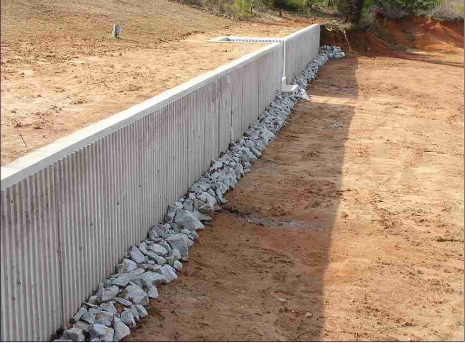
An unreinforced masonry retaining wall is a type of retaining wall constructed without the incorporation of steel reinforcement. These walls are typically built using materials like bricks, concrete blocks, or natural stones. Unreinforced masonry retaining walls are often chosen for very short walls due to their simplicity and cost-effectiveness.
For retaining walls with a height of between (1-2m), the additional reinforcement typically provided in concrete retaining walls may be deemed unnecessary as the self-weight of the masonry itself can provide adequate stability. While unreinforced masonry retaining walls may lack the structural complexity required for taller structures, they can be a practical and economical solution for short walls, providing effective soil retention in landscaping, garden terraces, or other applications where the height of the wall is minimal. However, it’s essential to ensure that such walls are appropriately designed and comply with local building codes to guarantee safety and stability.
Design Principles
Unreinforced masonry retaining walls typically rely on the compressive stress within generated due to their self-weight to maintain stability and integrity. The tension design strength of masonry walls is low, thus not exploited when designing masonry retaining walls. This is primarily due to the risk of cracking and eventual failure of the spine of the wall due to shear.
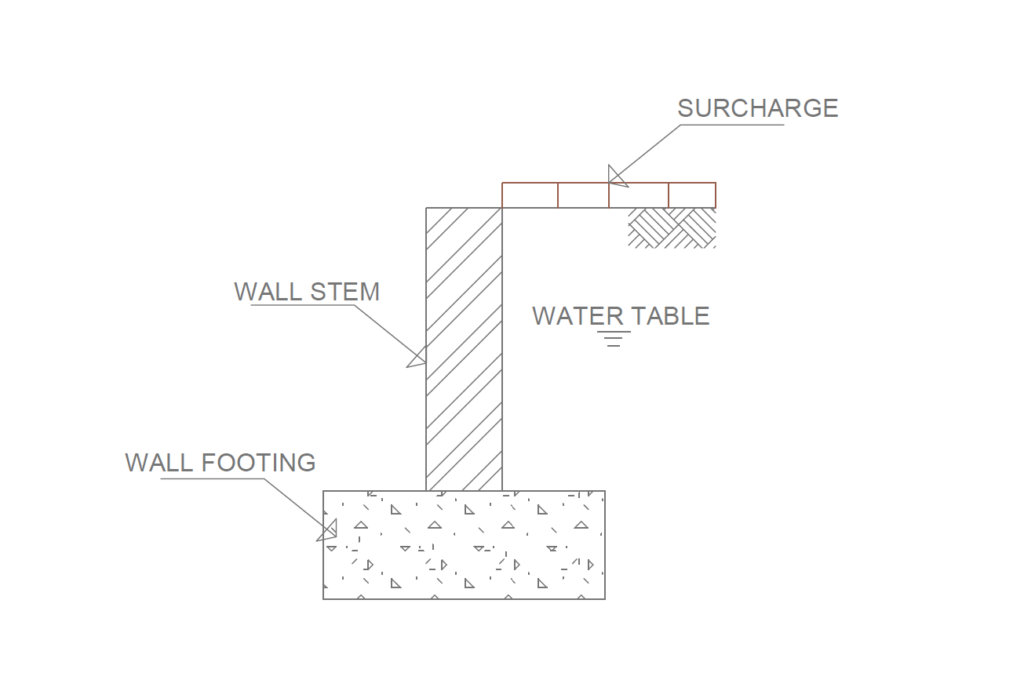
Note that this article is principally concerned with the design of the masonry within the assembly of the retaining wall. The design of the wall’s footing and the way it interacts with the substrate in which it is placed are not covered. These subjects are addressed in a previous article on retaining wall (See: Designing a reinforced concrete retaining wall). The key components of an unreinforced masonry retaining wall are described in (Figure 1).
Forces on an Unreinforced Retaining Wall
The forces applicable to unreinforced masonry retaining walls are generally not different from those of traditional structures. How to derive these forces have been covered in a previous article. (See: Derivation of Actions on Retaining Walls).
For simplicity, the lateral actions that are typically applied to an unreinforced masonry retaining wall will arise from three different sources:
- earth pressure
- hydrostatic pressure
- surcharge.
The primary lateral force on a retaining wall is earth pressure, which requires modification of the soil through treatment or strengthening for effective alleviation. Ensuring accurate modeling of this action is crucial to confidently resist resulting stresses in the wall.
Hydrostatic pressure is an action that is applied where there is a high-water table, and the retaining wall is sufficiently waterproofed or ‘tanked’ to prevent the water from seeping through the masonry. In most cases, hydrostatic pressure is relieved by the deployment of weep holes through the retaining wall or the introduction of a land drain that gathers most of the groundwater, then distributes it away from the wall (Figure 2).
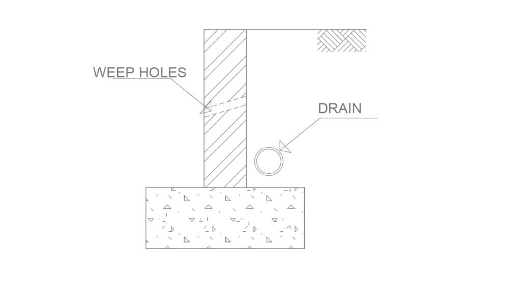
Such measures are considered good practice, as the build-up of hydrostatic pressure behind an unreinforced masonry wall is undesirable due to the impact it has on the soil and the retaining wall’s ability to resist shear via the interaction between the footing and the substrate it rests on. It should be noted, however, that these installations need to be maintained to ensure they function as intended. For example, weep holes need to be kept clear of debris as far as possible and the land drain needs to be kept free of sediment.
Surcharges are variable actions that are applied to the soil on the retained side of the retaining wall. These exert a lateral pressure on the wall, the magnitude of which is based on the vertically applied variable action onto the surface of the retained material. The way in which this action is spread into the soil and onto the wall depends on the properties of the material that the wall is retaining.
Failure modes
A retaining wall can fail in three ways: overturning, sliding, and spine. Overturning and sliding, detailed in Structural Analysis of Retaining Walls, apply equally to a masonry retaining wall. However, spine failure is treated differently in an unreinforced masonry retaining wall compared to a reinforced concrete one. BS EN 1996-1-1, Clause 6.3.4.(1), prohibits tension in the unreinforced masonry wall under lateral earth pressures.
Without reinforcement, strengthening the wall involves altering its geometry through the introduction of piers or overall wall thickening. If space or cost constraints make these methods infeasible, vertical reinforcement may be considered, though this would go beyond the scope of this article.
Movement joints
Unreinforced masonry retaining walls present a distinctive requirement for incorporating vertical movement joints. The frequency of these joints relies on the type of masonry in the wall. In the case of concrete blockwork, vertical movement joints are essential at 9m intervals when there is no reinforcement in the bed joints. The distance between joints can be extended if reinforcement is used, depending on the type of bed joint reinforcement. For walls predominantly made of clay bricks, the spacing between vertical movement joints can be up to 15m, with the possibility of further extension if mortar bed reinforcement is utilized.
Movement joints can be perceived as potential weak points in the wall, disrupting its continuity and introducing higher stresses when subjected to earth pressure actions. To bolster these joints, de-bonded ties may be employed to establish shear resistance across the joint. Another option involves installing a pier near a movement joint to enhance the wall’s strength at that specific location. Additional details on constraining distances between movement joints in masonry walls can be found in Clause 2.3.4.2(2), Table NA.1 of the UK National Annex to BS EN 1996-2.
Design Strength
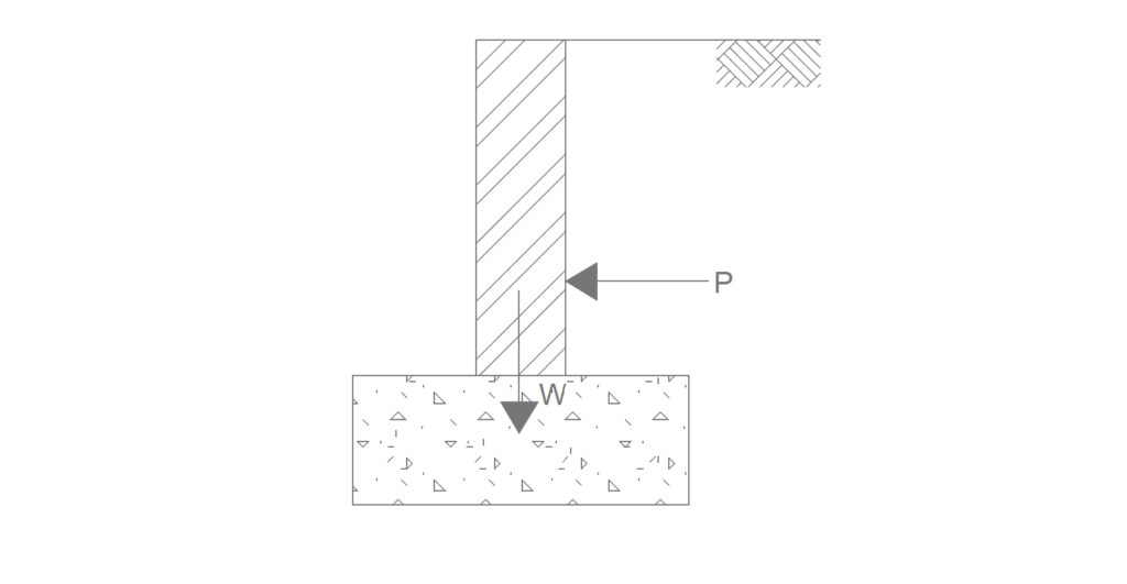
This section largely covers topics previously addressed in the previous article: Designing a Laterally Loaded Masonry Wall. Similar to other masonry walls, an essential consideration is assessing whether the resultant forces fall outside the middle third of the wall, potentially causing tension. If the mass of the wall ensures that lateral forces remain within the middle third, no further checks on the wall are necessary. The design approach for unreinforced masonry walls centers on their geometry. The wall’s geometry should prevent tension by utilizing its self-weight to counteract lateral forces from soil pressure. This involves creating a thick wall where the resultant force aligns within the middle third of its footing (see Figure 3)
Worked Example
Determine the necessary thickness for an unreinforced masonry retaining wall in increments of 100mm. Assuming the wall is 1200mm high, constructed from dense blockwork (23kN/m3) with 10mm bed joints using M12 mortar. It supports soil with a density of 18kN/m3 and a surcharge of 2.5kN/m2 (Figure 4). (N:B Coefficient of active pressure =0.33)
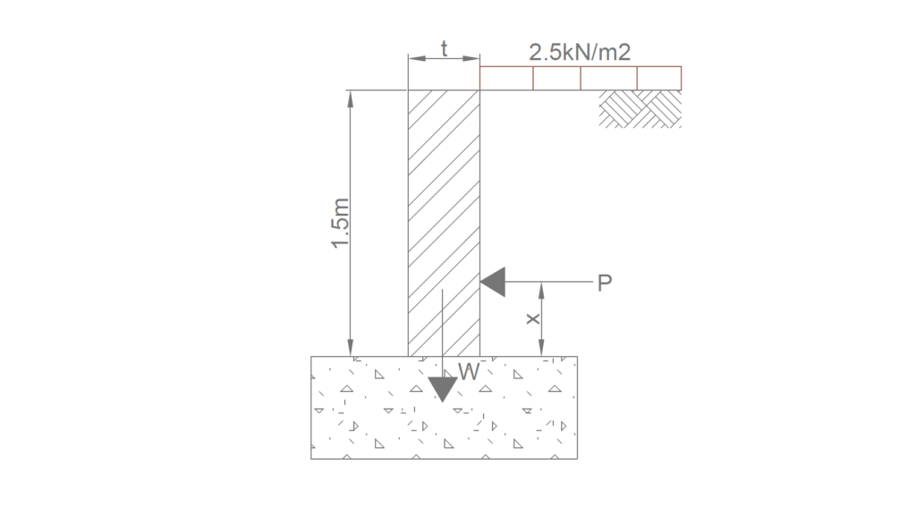
Lateral Forces on Wall
The lateral forces on the wall are of two types: from the backfill and the from surcharge applied unto the backfill.
p =p_{s} +p_{sur}p_s =0.5k_a\gamma_sh^2 = 0.5\times0.33\times18\times 1.5^2 = 6.7kN/m^2
p_{sur} = k_aq h = 0.33\times 1.5 \times2.5 = 1.24kN/m^2p= 6.7 +1.24 =7.9kN/m^2
Determine no Tension in Wall
To ensure that there’s no tension in the wall, we must ensure that location of the value of x defined in figure 4 is less than the eccentricity in the wall due to the applied loads.
Location of x
x=\frac {1.5 +(2.5/18)}{3} = 0.54mEccentricity
Try 900mm Thick Wall
middle \quad third =\frac{0.9}{6} =0.15me=\frac{7.9\times 0.54}{1\times23\times1.5} = 0.137 <0.15 \quad o.kSources & Citations
- BS EN 1996-1-1:2005+A1:2012 Eurocode 6: Design of masonry structures. General rules for reinforced and unreinforced masonry structures
- The Institution of Structural Engineers (2018) Technical Guidance Note (Level 2). The Structural Engineer 100(10) pp 28 -31.
Can you send me an example with water table