Crane supporting structures are among the most demanding structural systems encountered in industrial engineering because they must safely resist complex combinations of static, dynamic, horizontal, and cyclic loads throughout their operational life.
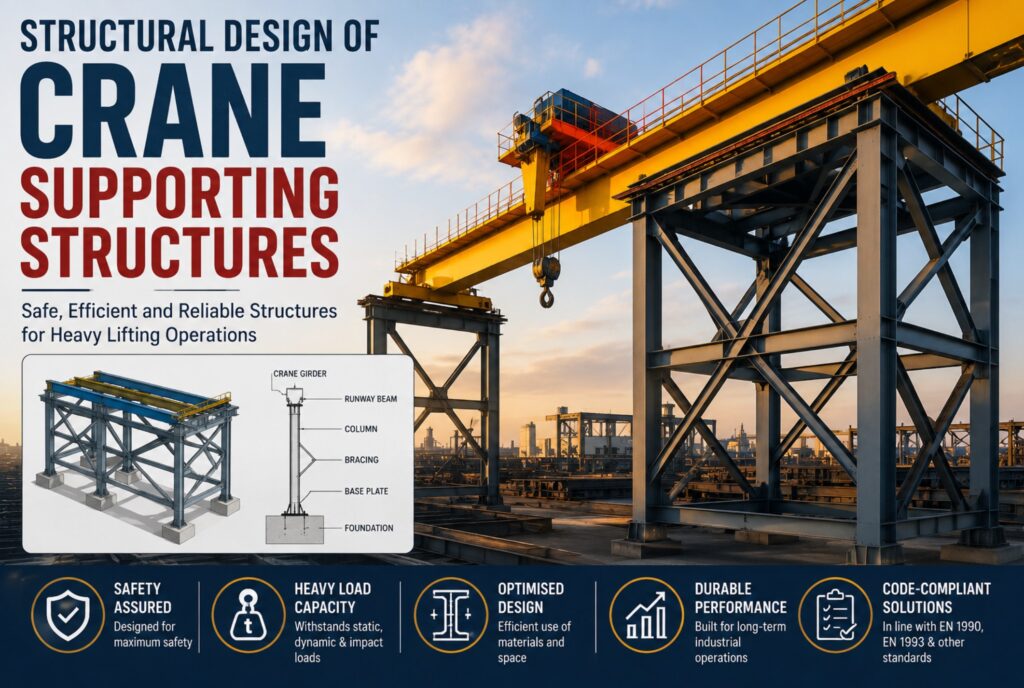
Industrial facilities, manufacturing plants, warehouses, ports, power stations, steel mills, and fabrication workshops frequently rely on cranes for lifting, transporting, and positioning heavy loads. While considerable attention is often given to the design and selection of the crane itself, the supporting structure that carries and transfers crane loads to the foundation is equally important.
Unlike conventional building structures, crane supporting structures are subjected to highly variable, repetitive, and dynamic loads that require specialized design considerations beyond those used for ordinary floor systems or industrial frames.
Crane Supporting Structures
Crane supporting structures are structural systems specifically designed to support, guide, and transfer loads generated by cranes to the primary structural framework and ultimately to the foundation. Unlike conventional building members that primarily resist static gravity loads, these structures must accommodate continuously changing moving loads together with dynamic effects generated during crane operation.
A typical supporting system consists of runway beams, supporting columns, bracing systems, connections, foundations, and runway rails. Together, these elements provide a stable path through which vertical wheel loads, horizontal forces, and dynamic actions are transmitted safely into the ground.
Depending on the type of crane and its operational requirements, the supporting structure may form part of the building frame or exist as an independent structural system. Regardless of the configuration adopted, the supporting structure must maintain adequate alignment, stiffness, and structural integrity throughout repeated loading cycles.
Types of Crane Supporting Structures
The structural arrangement depends on the crane type, lifting capacity, operational requirements, and the overall layout of the facility.
Building-Integrated Crane Runway Structures
In many industrial buildings, overhead travelling cranes are supported directly by the building frame. Runway beams are mounted on brackets connected to steel or reinforced concrete columns, allowing the crane to travel along the length of the building.
This arrangement makes efficient use of the existing structural framework but requires the building to resist significant additional vertical and horizontal loads generated during crane operation.
Freestanding Crane Supporting Structures
Where crane loads are too large for the building frame or where operational flexibility is required, independent crane supporting structures may be constructed.
These systems consist of dedicated columns, runway beams, bracing systems, and foundations that function independently of the surrounding building. Because crane actions are isolated from the primary building frame, structural design can be optimised specifically for crane loading.
Gantry Crane Supporting Structures
Gantry cranes travel on rails supported at ground level rather than elevated runway beams. Their supporting structures generally comprise reinforced concrete foundations, rail beams, pile-supported systems where necessary, and ground-level support arrangements capable of resisting concentrated wheel loads and horizontal actions.
These systems are widely used in ports, container terminals, precast concrete yards, shipyards, and heavy manufacturing facilities.
Jib Crane Supporting Structures
Jib cranes are supported by either freestanding columns or building columns and provide rotational lifting within a limited working radius.
Although their lifting capacities are generally smaller than those of overhead travelling cranes, they introduce significant overturning moments and torsional forces into their supporting structures.
Monorail Crane Systems
Monorail cranes travel along a single runway beam and are commonly used in assembly plants, warehouses, and production lines where loads follow predetermined paths.
Because loading is concentrated on a single beam, careful attention must be given to local bending, deflection, vibration, and connection design.
Loads Considered in Crane Supporting Structure Design
Unlike ordinary building structures, crane supporting systems are subjected to numerous load components that may act simultaneously. Proper identification of these actions forms the basis of safe structural design.
Dead Loads
Dead loads include the self-weight of runway beams, rails, brackets, columns, bracing systems, and other permanent structural components.
These loads remain essentially constant throughout the life of the structure and form part of every load combination.
Crane Self-Weight
The self-weight of the crane contributes significantly to wheel loads transmitted to the runway beams. This includes the bridge girder, end trucks, trolley, lifting mechanism, electrical equipment, and other permanently attached components.
As the crane moves, these wheel loads travel continuously along the runway, producing changing bending moments and shear forces.
Lifted Loads
The lifted load represents the most obvious variable action acting on the structure.
Its magnitude depends on the crane’s rated lifting capacity, although structural design must also consider partial loading conditions because the most critical structural effects do not always occur at maximum lifting capacity.
Wheel loads vary continuously depending on both the crane position and trolley location.
Dynamic Impact Loads
Crane operation involves acceleration, deceleration, hoisting, lowering, and sudden changes in loading conditions.
These actions generate dynamic amplification beyond the static lifted load. Accordingly, design standards specify dynamic factors that increase design loads to account for impact effects during normal crane operation.
Ignoring these dynamic effects may result in unconservative designs despite satisfying static strength requirements.
Horizontal Transverse Loads
As the trolley moves across the crane bridge, horizontal transverse forces develop perpendicular to the runway.
These forces arise from acceleration, deceleration, load swing, and operational irregularities and are transferred through runway beams into supporting columns and bracing systems.
Proper lateral bracing is therefore essential for maintaining structural stability.
Longitudinal Braking Loads
When the crane accelerates or brakes along the runway, longitudinal forces develop parallel to the crane track.
These forces must be transferred through the runway system into the building bracing or dedicated longitudinal stability system without causing excessive movement or structural distress.
Skewing Forces
Minor misalignments between crane wheels and runway rails often generate skewing forces.
Although relatively small compared with vertical wheel loads, repeated skewing actions contribute significantly to fatigue damage, rail wear, and connection deterioration throughout the service life of the structure.
Consequently, structural engineers should not overlook these forces during design.
Fatigue Loading
One of the defining characteristics of crane supporting structures is their exposure to repeated loading throughout their service life. Unlike conventional buildings, where many structural members experience relatively constant loading, crane runway beams, brackets, connections, and supporting columns are subjected to thousands or even millions of loading cycles resulting from continuous crane operation.
Repeated wheel loads can initiate microscopic cracks at stress concentration points such as welded details, bolt holes, stiffener terminations, and geometric discontinuities. Over time, these cracks may propagate under cyclic loading until structural failure occurs, even when the applied stresses remain well below the material’s static strength.
For this reason, fatigue assessment forms a critical component of crane supporting structure design. Eurocode 3 (EN 1993-1-9) provides detailed fatigue design procedures, including fatigue categories for welded and bolted connections, stress range calculations, and verification methods. Structures supporting cranes operating continuously in steel plants, ports, heavy manufacturing facilities, or shipyards often require particularly rigorous fatigue assessments because of the high number of stress cycles they experience during their design life.
Structural Behaviour of Crane Supporting Structures
The behaviour of crane supporting structures differs significantly from that of conventional industrial buildings because the applied loads are highly dynamic, mobile, and repetitive. Rather than remaining stationary, crane loads move continuously along the runway, causing bending moments, shear forces, and support reactions to vary throughout the structure.
Runway beams experience repeated flexural loading as wheel loads travel from one end of the beam to the other. Supporting columns resist not only gravity loads but also substantial horizontal forces generated by crane acceleration, braking, and skewing. Bracing systems stabilise the structure by transferring longitudinal and transverse forces to the foundations while maintaining alignment of the runway.
The structural response depends not only on member strength but also on the stiffness of the entire system. Excessive flexibility may lead to noticeable runway deflections, rail misalignment, increased wheel loads, and accelerated wear of crane components. Consequently, serviceability often governs the design of crane supporting structures as much as ultimate strength.
Because crane operations occur repeatedly throughout the life of a facility, engineers must evaluate the cumulative effects of cyclic loading, vibration, and fatigue rather than focusing solely on isolated loading events.
Key Structural Design Considerations
Strength
All structural members must possess sufficient strength to resist the most unfavourable combinations of vertical, horizontal, dynamic, and environmental loads without exceeding the ultimate limit state.
Runway beams, supporting columns, brackets, bracing members, and foundations are all designed to resist the forces generated during both normal operation and exceptional loading conditions.
Serviceability
Serviceability requirements are particularly important for crane supporting structures because excessive deflections directly affect crane operation.
Even relatively small runway misalignments may increase wheel wear, produce uneven load distribution, reduce lifting precision, and shorten the service life of mechanical components. Accordingly, allowable deflection limits for runway beams are generally more restrictive than those applied to conventional floor beams.
Engineers must therefore verify vertical deflections, horizontal displacements, differential settlements, and rail alignment throughout the design process.
Vibration Control
Moving cranes generate vibrations that propagate throughout the supporting structure. If the natural frequency of the structure approaches the excitation frequency generated during crane operation, resonance may occur, resulting in excessive vibration amplitudes.
Vibration can adversely affect structural performance, operator comfort, precision lifting operations, and the durability of welded and bolted connections. Structural dynamic analysis may therefore be required for heavy-duty crane installations or structures supporting high-speed automated cranes.
Connection Design
Connections are among the most critical components of crane supporting structures because they transfer large cyclic forces between structural members.
Poorly detailed welded or bolted connections frequently become the locations where fatigue cracking first develops. Engineers therefore minimise stress concentrations through appropriate detailing, adequate weld profiles, smooth force transfer paths, and suitable stiffener arrangements.
Where heavy-duty cranes operate continuously, fatigue-resistant connection details become just as important as the strength of the primary structural members.
Foundation Design
Crane loads are ultimately transferred into the supporting foundations through columns or dedicated support frames.
Foundations must safely resist concentrated wheel loads, overturning moments, horizontal forces, and repeated cyclic loading without excessive settlement. Differential settlement between adjacent foundations can produce runway misalignment, increasing crane wheel stresses and adversely affecting operational performance.
Where poor ground conditions exist, piled foundations may be required to maintain acceptable alignment and long-term serviceability.
Common Design Challenges
Designing crane supporting structures involves several practical challenges beyond satisfying code requirements.
One common issue is underestimating dynamic effects by considering only static crane loads. Failure to account for impact factors and repeated loading can result in unconservative designs that experience premature fatigue cracking.
Construction tolerances also present challenges. Minor inaccuracies in column alignment, runway beam installation, or rail positioning can lead to increased wheel loads, skewing forces, and operational difficulties.
Another challenge involves coordinating the structural design with crane manufacturers. Differences between assumed design loads and actual crane characteristics may require costly modifications if identified late in the project.
Future operational changes must also be considered. Industrial facilities often replace cranes with larger units as production demands increase. Designing supporting structures with sufficient reserve capacity or allowing for future strengthening can significantly reduce long-term upgrade costs.
Conclusion
Crane supporting structures are among the most demanding structural systems encountered in industrial engineering because they must safely resist complex combinations of static, dynamic, horizontal, and cyclic loads throughout their operational life. Unlike conventional building structures, they are continuously subjected to moving wheel loads, impact effects, braking forces, skewing actions, fatigue loading, and environmental influences that require specialised design approaches.
Also See: Dispersal of Traffic Load on Buried Culverts
Sources & Citations
- EN 1990:2002 – Eurocode: Basis of Structural Design.
- EN 1991-3:2006 – Eurocode 1: Actions on Structures – Actions Induced by Cranes and Machinery.
- EN 1993-1-1:2005 & EN 1993-1-9:2005 – Eurocode 3: Design of Steel Structures.
- ISO 4301-1 – Cranes – Classification.
- Crane Manufacturers Association of America (CMAA). Specification No. 70 – Specifications for Top Running Bridge & Gantry Cranes.
