Construction joints are necessary in many reinforced concrete projects. However, their performance depends on proper design, detailing and execution.
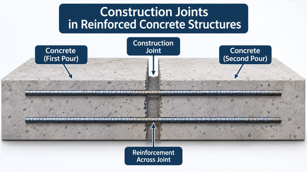
Construction joints form whenever concrete placement stops and work resumes later. They allow contractors to divide large concrete elements into manageable pours. They also accommodate practical limits involving labour, equipment, transportation and concrete supply. Although construction joints are common, their locations and details require careful engineering consideration.
A construction joint creates an interface between concrete placed at different times. This interface must transfer the forces required by the structural design. It must also maintain adequate durability and, where necessary, watertightness. Poor joint detailing or preparation can weaken an otherwise satisfactory reinforced concrete member.
Structural engineers should therefore treat construction joints as part of the structural design. Their drawings should identify suitable locations and provide the necessary reinforcement details. Contractors must then prepare and execute each joint correctly. This coordination helps maintain structural continuity throughout construction.
Structural Role of a Construction Joint
A construction joint marks the boundary between two separate concrete placements. Unlike an expansion or contraction joint, it does not necessarily permit movement between adjoining concrete sections.
The structural design generally requires both sections to act together. Reinforcement crossing the interface helps maintain this continuity. The concrete interface must also transfer the relevant forces.
These forces may include:
- Shear forces acting along the interface.
- Tensile forces resisted by reinforcement crossing the joint.
- Compression forces transferred through direct contact.
- Local forces caused by bending, torsion or restraint.
The actual requirements depend on the structural element and its loading. A construction joint in a lightly loaded ground slab differs from one in a transfer beam. A joint within a retaining wall also presents different durability requirements.
The engineer must understand these differences before approving a joint location. Treating every construction joint as a simple concrete interface can create serious structural weaknesses.
Selecting Suitable Locations for Construction Joints
Joint location affects how effectively a reinforced concrete element transfers loads. Designers should consider the distribution of bending moments, shear forces and reinforcement. They should also consider the proposed construction sequence.
For beams, designers often place construction joints within regions of relatively low shear. However, the actual location must follow structural analysis and detailing requirements. A convenient position for the contractor may not provide a suitable structural arrangement.
Slabs require similar consideration. Large floor plates may need several planned concrete pours. Designers should coordinate these pour boundaries with the reinforcement arrangement and support conditions. They should also avoid unnecessary joints around heavily loaded columns and transfer zones.
Columns and walls usually require horizontal construction joints between successive lifts. Contractors commonly place these joints at floor levels or other practical construction stages. The engineer must ensure that the joint does not compromise force transfer or reinforcement continuity.
For retaining walls, water tanks and basement structures, joint location also affects water penetration. Designers should minimise unnecessary joints and coordinate their positions with waterstops. They should also consider hydrostatic pressure and the direction of potential leakage.
The contractor should not relocate an approved joint without the engineer’s consent. A change in joint position may affect structural behaviour and reinforcement detailing.
Shear Transfer Across Construction Joints
Shear transfer represents one of the main structural considerations at a construction joint. The interface must transfer the shear forces assumed during design. Its resistance depends on several factors, including surface condition and reinforcement crossing the joint.
Eurocode 2 addresses shear transfer between concrete cast at different times. Its interface shear provisions consider surface roughness, concrete strength, normal stress and reinforcement crossing the interface.
The shear-friction approach provides a useful explanation of this behaviour. Reinforcement crossing the joint restrains relative movement between the adjoining concrete sections. This restraint generates clamping action across the interface. Surface roughness also contributes through aggregate interlock.
A smooth interface offers less resistance than a properly roughened surface. Designers should therefore specify the required surface condition. They must also check the interface using the applicable design standard.
The engineer should not assume that reinforcement alone guarantees adequate shear transfer. The interface must satisfy the relevant design requirements. Similarly, roughening the surface does not remove the need for adequate reinforcement.
Where the joint carries significant shear, the design may require additional reinforcement. The engineer should check the available interface resistance against the applied shear force. The calculation should reflect the actual surface preparation and reinforcement arrangement.
Surface Preparation Before the Next Concrete Pour
Surface preparation directly affects the quality of the construction joint. Concrete laitance, loose particles and contamination can weaken the interface. The contractor must remove these materials before placing fresh concrete.
The preparation procedure should include the following steps:
- Remove weak surface concrete and laitance.
- Expose sound concrete and the specified aggregate profile.
- Remove dust, debris, oil and other contaminants.
- Clean the reinforcement without damaging its bond surface.
- Remove standing water before placing fresh concrete.
- Follow the approved specification for the required moisture condition.
The required surface roughness depends on the design and project specification. A deliberately roughened surface provides better mechanical interlock than a smooth formed face.
Contractors may use suitable mechanical preparation methods to achieve the specified profile. However, excessive impact can damage sound concrete or loosen aggregate. The method should therefore suit the concrete condition and joint requirements.
The contractor should also avoid applying bonding agents without approval. Some projects specify cementitious bonding materials or proprietary products. Their use must follow the manufacturer’s instructions and project requirements.
The engineer should inspect the prepared joint before the next pour. This inspection provides an opportunity to identify contamination, inadequate roughness or damaged reinforcement.
Reinforcement Detailing and Continuity
Reinforcement crossing a construction joint plays an important role in structural continuity. It helps transfer tension and contributes to shear resistance. Designers must therefore maintain the required reinforcement arrangement across the interface.
Main reinforcement should continue through the joint where the design requires continuity. Where bars need splicing, the designer should specify suitable lap lengths or mechanical couplers. The detailing must satisfy anchorage, lap and reinforcement spacing requirements.
Contractors should not cut or reposition reinforcement simply to simplify concrete placement. Such changes can reduce the available resistance across the joint. They may also create congestion or inadequate concrete cover.
The drawings should clearly show reinforcement passing through each planned joint. They should also identify any additional bars required for shear transfer or local force resistance.
Reinforcement congestion deserves particular attention around beam-column joints, transfer beams and heavily reinforced walls. Congested detailing can prevent proper concrete placement and compaction. Designers should coordinate bar arrangements with the actual construction sequence.
Managing Unexpected Interruptions During Concrete Placement
Not every interruption creates an unacceptable construction joint. The outcome depends on the concrete condition and the time before placement resumes. Temperature, mix characteristics, admixtures and site conditions all influence setting behaviour.
An interruption becomes more serious when the earlier concrete begins to stiffen. Fresh concrete may then fail to integrate properly with the existing surface. This can create a weak interface commonly described as a cold joint.
Contractors should prepare contingency arrangements before major concrete pours. These arrangements should address pump breakdowns, batching delays, equipment failure and traffic interruptions. The pour plan should also identify suitable emergency joint locations.
If an unexpected interruption occurs, the site team should inform the supervising engineer. They should record the interruption time, concrete condition and affected location. The engineer can then determine whether the contractor should resume placement or form a construction joint.
The contractor should not conceal an unplanned joint beneath subsequent concrete. The engineer must assess its location and determine the required remedial measures. Depending on the circumstances, these may include surface preparation, additional reinforcement or specialist repair.
Construction Joints in Watertight Structures
Construction joints require additional attention in water-retaining and below-ground structures. Water can pass through poorly prepared interfaces and compromise the structure’s serviceability. Persistent leakage may also accelerate reinforcement corrosion.
Designers should minimise unnecessary joints in tanks, basements and retaining structures. Where joints remain necessary, the design should provide suitable waterstops or waterbars. These components interrupt potential leakage paths through the concrete.
Waterstops may consist of PVC, rubber or metal products. The selected type should suit the expected water pressure, joint arrangement and construction method. The detailing must also address corners, intersections and changes in direction.
Correct installation matters as much as product selection. Contractors must secure waterstops against displacement during concrete placement. They must also ensure proper compaction around the waterstop. Poor compaction can create voids that defeat the intended protection.
The designer should coordinate waterstop details with reinforcement and formwork. Congestion around the joint can make installation difficult. Early coordination helps avoid site modifications and poor workmanship.
Inspection and Quality Control
Effective quality control begins before the first concrete pour. The project team should review joint locations, reinforcement details and construction sequences. The contractor should also confirm that suitable preparation equipment and materials are available.
Before placing fresh concrete, the supervising engineer should verify:
- The joint location matches the approved drawings.
- The existing concrete has adequate strength and condition.
- The surface has the specified roughness and cleanliness.
- Reinforcement remains continuous and correctly positioned.
- Waterstops and embedded components have secure support.
- The contractor has removed loose material and standing water.
Photographs and inspection records should document the completed preparation. These records provide useful evidence during subsequent quality reviews.
The contractor should also record concrete placement times and any interruptions. Such records help identify potential cold joints and explain unusual site conditions. Where defects appear, the engineer can investigate them using the available construction records.
The project specification should establish clear inspection and acceptance requirements. It should also identify who can approve changes to joint locations or preparation methods.
Conclusion
Construction joints are necessary in many reinforced concrete projects. However, their performance depends on proper design, detailing and execution. Engineers must consider joint location, interface shear resistance and reinforcement continuity. They must also account for durability and watertightness where relevant.
Contractors must prepare each interface carefully before placing fresh concrete. They should follow approved procedures and report unexpected interruptions promptly. Good inspection records also help demonstrate compliance with the design requirements.
A construction joint should never become an uncontrolled weakness within a structural element. Proper coordination between the designer, contractor and supervising engineer helps preserve the intended structural performance.
Also See: Structural Design Aspects of Liquid Retaining Structures
Sources & Citations
- British Standards Institution. BS EN 1992-1-1: Eurocode 2: Design of Concrete Structures – General Rules and Rules for Buildings.
- European Committee for Standardization. EN 13670: Execution of Concrete Structures.
- American Concrete Institute. ACI 318: Building Code Requirements for Structural Concrete.
- American Concrete Institute. ACI 301: Specifications for Concrete Construction.
- CIRIA. CIRIA Report 139: Water-Resisting Basements.
