This article provides a comprehensive guide to the dispersal of traffic loads on culverts. It explains the underlying principles, and offers a worked example to demonstrate the practical application of these concept.
Culverts are integral to modern infrastructure, allowing the passage of water beneath roads, railways, and embankments. Beyond managing water flow, they also bear substantial traffic loads. These traffic loads must disperse efficiently for the culvert design to be correct. Poorly designed culverts can lead to structural damage, high maintenance costs, and even catastrophic failures.
Understanding the mechanics of traffic load dispersal is crucial for designing culverts that can endure various traffic and environmental conditions. Engineers rely on careful calculations and design strategies to account for factors like soil properties, traffic magnitude, and culvert depth. Proper load dispersal ensures the forces exerted on the culvert are evenly and safely distributed.
This article provides a comprehensive guide to the dispersal of traffic load on culverts. It explains the underlying principles, highlights the factors influencing load transfer, and offers a worked example to demonstrate the practical application of these concepts. By the end, readers will appreciate the complexities of culvert design and the importance of efficient load distribution.
How Traffic Loads Are Dispersed on Culverts
When vehicles travel over a road, their weight applies force to the surface and transmits through the soil layers to the culvert. This transmission occurs indirectly through load dispersal, a process that spreads concentrated forces from the vehicle over a larger area, reducing the intensity of the force on the culvert crown. We typically use the load increment method or Boussinesq’s equation for this, with increment method being the simpler option. This article focuses on the former for its ease of application.
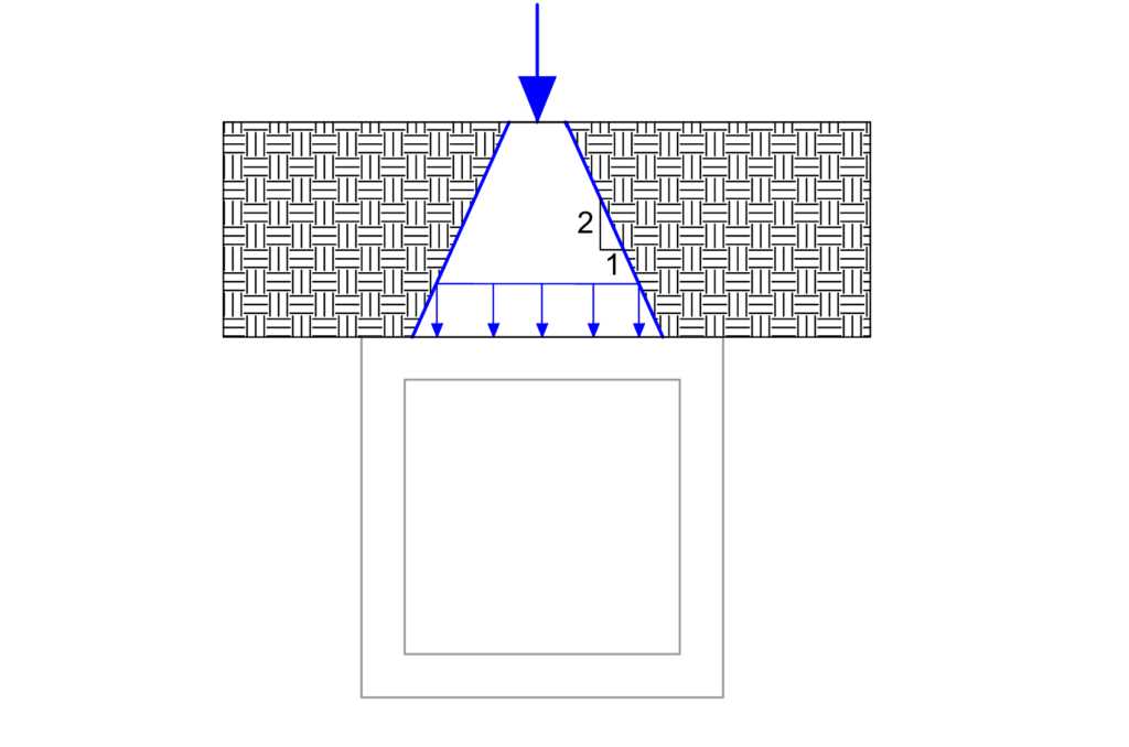
The soil above the culvert plays a critical role in spreading traffic load. As the load travels downward, it disperses outward in a cone-like pattern. The angle of dispersion is commonly assumed to be 30°, although it can vary depending on the soil type and compaction. With every unit of depth, the load spreads outward by an equal unit, increasing the area over which the force acts.
For example, when a wheel load applies to a road surface and the culvert lies 1.5 meters below, the load at the culvert crown spreads over a larger area than the original wheel contact area. This dispersion reduces the pressure acting directly on the culvert.
The material and shape of the culvert also influence how it handles loads. Rigid culverts, such as those made of reinforced concrete, can resist significant forces and distribute them evenly to the surrounding soil. Flexible culverts, like corrugated metal pipes, rely on the soil for additional support. Their design allows them to deform slightly under load, transferring stress to the surrounding compacted soil.
HA and HB Carriageway Loading
This section explains the loading standards for box culverts, focusing on HA and HB loading as outlined in BD 37. These standards guide the design of culverts to handle various traffic conditions.
HA Loading
For cover depths of 0.6 m or less, HA loading consists of uniformly distributed loads (UDL) and knife-edge loads (KEL). At these depths, no dispersion through the fill occurs for either the UDL or KEL loads.
For cover depths greater than 0.6 m, the HA UDL/KEL combination no longer suffices to represent traffic loading. In these cases, authorities substitute the HA UDL/KEL with 30 units of HB loading, which disperse through the fill to account for the increased depth.
Additionally, if a single HA wheel load of 100 kN produces a more critical effect on the structure than the UDL/KEL or 30 units of HB loading, engineers consider it.
HB Loading
For trunk roads and motorways, the standard HB loading requirement is 45 units (Figure). These roads typically experience heavy traffic volumes, including large and heavy vehicles, making it essential to design culverts and similar structures to withstand substantial stresses. This higher loading standard ensures the safety and durability of the infrastructure, even under the most demanding conditions.
On other public highways, which typically experience lighter or less frequent traffic, authorities require a minimum of 30 units of HB loading. This threshold ensures adequate protection for structures while considering the occasional presence of heavy vehicles. If higher loading conditions are expected, the overseeing authority sets a higher HB loading value to meet the roadway’s specific demands.
Furthermore, all structures designed to accommodate HA loading must also include a minimum of 30 units of HB loading in their design considerations. This ensures that even under nominal traffic conditions, the structure remains resilient and capable of handling heavier or unexpected loads without compromising safety or performance.
Load Dispersal Rules
Load dispersal follows strict guidelines to ensure uniform application of pressure across the structure.
Wheel and Axle Loads Through the Fill
At ground level, wheel loads distribute uniformly over a contact area determined by an effective pressure of 1.1 N/mm². This initial distribution accounts for the direct application of the load on the surface, ensuring a controlled transfer to the underlying fill material.
As the load travels through the fill, it disperses both longitudinally and transversely at a slope of 2:1 (two units vertically to one unit horizontally). This dispersion reduces the load intensity and spreads it over a broader area before reaching the structure’s roof. When the dispersal zones of adjacent wheels overlap, the combined effect treats the load as uniformly distributed across the overlapping region. This combined approach ensures a more even application of stress across the structure’s surface, preventing localized pressure concentrations.
Wheel and Axle Loads Through the Roof
Upon reaching the roof level of the structure, the load undergoes further lateral dispersion. Here, the dispersal occurs at a 45° angle to the neutral axis of the roof slab. This additional spreading helps distribute the load uniformly across the roof, reducing the risk of stress concentrations and enhancing structural performance.
For a single wheel load, the total dispersed width at the roof is given by total width WA:
W_A=C+H+2h_{na}Where: C represents the contact patch width, H is the depth of cover, and hna is the depth from the top of the roof to its neutral axis, approximated as half the overall slab depth.
In the case of an axle load, the total dispersed width is calculated as:
W_B=C+(n-1)S+H+2h_{na}Here, n is the number of wheels on the axle, S is the spacing between adjacent wheels, C is the contact patch width, H is the depth of cover, and hna is the depth to the neutral axis.
Worked Example: Traffic Load on a Box Culvert
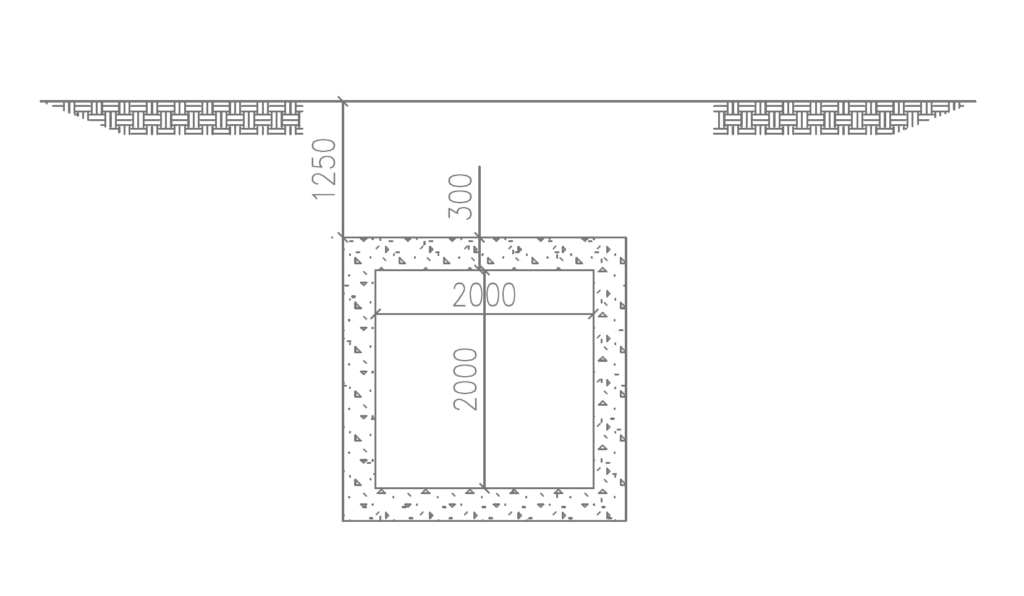
Consider a box culvert with a cover depth of 1.25m. The roof slab has a thickness of 300 mm, and its neutral axis is located at a depth of 150 mm from the top of the slab. Determine the critical imposed traffic load at the culvert crown, assuming:
- A single HA 100 kN wheel load.
- 45 HB load units (equivalent to 112.5 kN per wheel).
Step 1: HA 100 kN Wheel Load
Contact Area: The contact area at ground level is calculated assuming a uniform pressure of 1.1 N/mm2. Therefore, the contact area required:
= \sqrt\frac{100\times10^3}{1.1} =302mm \times 302mmAssuming the thickness of the culvert is 300mm and assuming the neutral axis lies at midpoint, utilizing the 2:1 rule to disperse the load to the crown of the culvert, we have the width at the culvert roof as:
w=302+1250+2\times(300/2)= 1.85m
Load Intensity for HA
P=\frac{100}{1.85\times1.85} =29.2kN/m^2Step 1: HB Axle Wheel Load
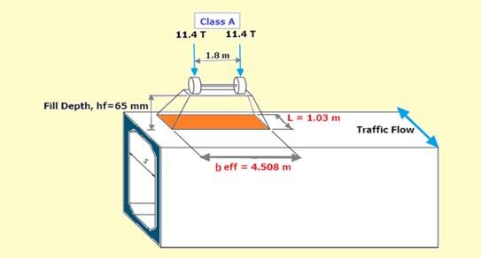
For an axle with two wheels, each wheel exerts a load of 112.5 kN, representing 45 units of HB loading. The contact patch area for each wheel is (See Figure ):
=45\times\frac{10}{4} =112.5kNContact Area: The contact area at ground level is calculated assuming a uniform pressure of 1.1 N/mm2. Therefore, the contact area required:
= \sqrt\frac{112.5\times10^3}{1.1} =320mm \times 320mmAs the wheel loads pass through the fill, their dispersal zones overlap, creating a combined distributed area. This is calculated by first determining the dispersed width at the roof. For an axle load, the total dispersed width is.
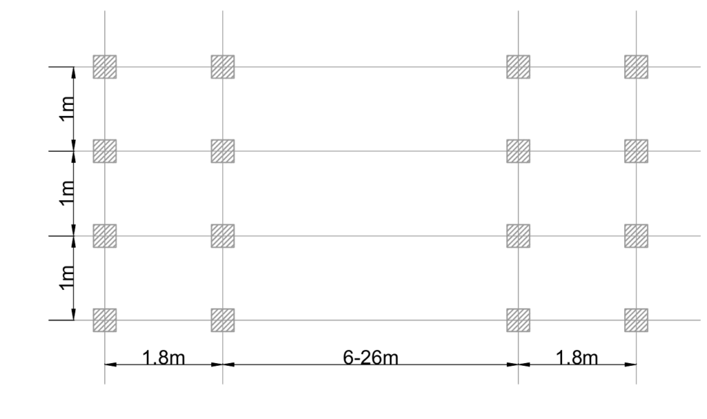
W_B=C+(n-1)S+H+2h_{na}In HB loading, each axle has 4 wheels spaced 1 meter apart. At a 1:2 gradient, the transverse dispersal lines overlap at a depth of 680 mm (1000 – 320), which is less than 1400 mm (depth of fill to neutral axis). Therefore, the overlap must be considered, requiring the inclusion of all 4 wheels.
In this example, the number of wheels, n, is 4 (representing the four wheels of the axle). The wheel spacing, S, is 1,000 mm, while the contact patch width, C, is 320 mm. The depth of cover, H, is 1,250 mm, and the depth to the neutral axis, hna is 150 mm, which is typically approximated as half the overall roof slab depth.
Therefore, the total width is:
W=320+(4-1)1000+1250+2(150)=4.87m
Longitudinal Dispersal Length:
In the longitudinal direction, there is no overlap because the pair of axles are spaced at 1.8m. Using a 1:2 gradient, the dispersal lines will overlap at (1800-320)=1480>1400
L=320+1250+(300/2)=1.85m
Load Intensity for HB
P_{Hb}=\frac{4\times112.5}{4.87\times1.85} = 49.9kN/m^2Conclusion
The dispersal of wheel and axle loads through the fill and roof slab plays a critical role in box culvert design. The provided worked example highlights the importance of fill depth and dispersal zones, especially when axle loads overlap. This overlapping effect creates a more uniform load distribution, reducing concentrated stress on the culvert’s roof slab and improving its performance. Engineers must understand these principles to design box culverts that meet loading standards and maintain structural integrity under varying traffic conditions.
See: How to Apply Loads on Box Culverts | Eurocodes
Sources & Citations
- British Standards Institution (BSI). (2008). BS EN 1991-2: Eurocode 1: Actions on structures – Part 2: Traffic load on bridges. BSI Standards Limited.
- Department for Transport. (2006). BD 37/01: Design of Road Pavements – HA and HB Loading. The Stationery Office.
- O’Rourke, M. J., & O’Neill, M. W. (2012). Box Culvert Design and Analysis. Civil Engineering and Structural Systems, 45(3), 215-227.
- Hughes, T. (2014). Traffic Load Distribution on Underground Structures. Journal of Structural Engineering, 38(2), 104-112.