Understanding load paths becomes particularly important when designing irregular reinforced concrete buildings. Changes in column positions, transfer floors, setbacks, large openings, irregular cores and uneven stiffness can all change the way forces move through a structure.
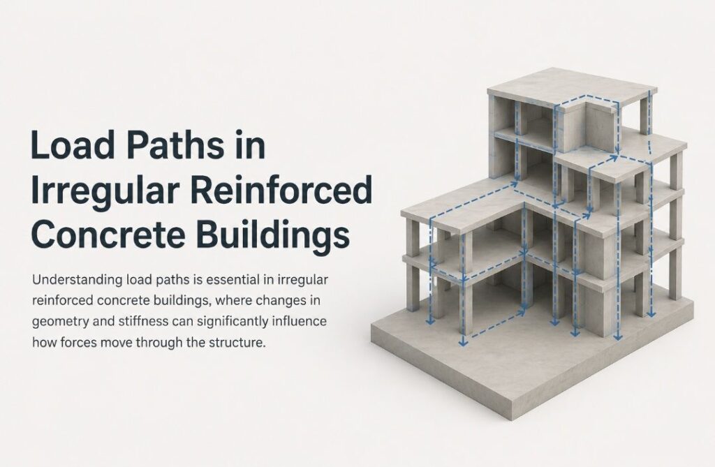
Every structural engineer learns early that loads must eventually reach the ground. In a simple reinforced concrete building, the route appears straightforward. Floor slabs transfer loads to beams, beams transfer loads to columns, columns transfer loads to foundations, and foundations transfer the forces into the soil. This basic arrangement works well when the building has a regular grid and the structural members remain reasonably continuous from one floor to another.
The situation becomes more complicated when the building is irregular. Columns may stop at certain floors, beams may transfer loads to other columns, floor plates may have large openings, setbacks may occur at upper levels, and shear walls may not align with the columns below. Architectural requirements often create these conditions. A building may have a large entrance lobby at ground floor, cantilevered upper floors, different column grids, or a tower rising from a much larger podium. Each change affects how the loads move through the structure.
For this reason, understanding the load path is one of the most important parts of structural design for an irregular reinforced concrete building. The engineer must not only check whether individual beams, slabs, columns and walls are adequate. The engineer must understand how forces move from one structural element to another and whether that route remains continuous, stable and capable of carrying the required forces. A member can pass its individual design check while the overall load path remains poorly arranged.
What is a Structural Load Path?
A load path is the route through which a force travels from where it is applied to the ground. In a building, gravity loads begin with the weight of finishes, partitions, occupants, equipment, walls and structural materials. These loads are collected by floor systems and transferred through the supporting members until they reach the foundations.
For a conventional reinforced concrete frame, a typical gravity load path starts at the floor slab. The slab carries its own weight and imposed loads and transfers them to beams or directly to columns, depending on the structural system. Beams then transfer their reactions to columns. Columns carry the accumulated axial forces down through the building and into the foundations. The foundations distribute those forces into the supporting soil.
Lateral loads follow a different route. Wind forces, for example, act on the building façade and are transferred through floor diaphragms to frames, shear walls or cores. These elements then carry the lateral forces towards the foundation, where the resulting horizontal forces and overturning effects must be resisted.
The load path therefore involves the entire structural system. It cannot be understood properly by looking at one beam or column in isolation.
Why Irregular Buildings Make Load Paths More Difficult
A regular building usually provides a reasonably direct and predictable load path. Columns remain vertically aligned, floor layouts repeat, and the structural system has similar geometry from one storey to another.
Irregular buildings introduce discontinuities into this arrangement. A column may terminate at the first floor because the architectural layout requires an open ground floor. A column above may then need to transfer its load through a deep beam or transfer slab to columns positioned elsewhere below.
The same issue occurs when a building has setbacks. Upper-floor columns may not align with lower-floor columns, forcing the engineer to introduce transfer elements. Large openings in slabs can also interrupt the normal distribution of forces.
These changes do not automatically make a building unsafe. They simply mean that the engineer must understand the resulting load path and design the discontinuity properly. Eurocode 2 recognises the need for local analysis where normal assumptions about structural behaviour do not apply, including areas around supports, concentrated loads, beam-column intersections, anchorage zones and changes in cross-section. (studylib.net)
Vertical Irregularity and Discontinuous Columns
One of the clearest examples of an irregular load path occurs when columns do not continue vertically through the building.
Consider a column carrying load from several upper floors. If that column terminates at a lower floor, the load has to move sideways before it can continue towards the foundation. A transfer beam may receive the column reaction and distribute it to columns below.
This creates a concentrated load and a different force distribution from that found in a conventional frame. The transfer beam may experience very high bending moments, shear forces and local stresses. The supporting columns may also receive substantially different loads from those assumed from a regular column grid.
The engineer must therefore design the transfer system as part of the complete load path. Checking the upper column alone is not sufficient. The transfer beam, supporting columns, connections and foundations must all be checked for the forces generated by the discontinuity.
Transfer Beams and Transfer Slabs
Transfer beams are commonly used where architectural requirements prevent columns from continuing directly to the foundation. They allow loads from upper-level columns or walls to be redirected towards lower-level supports.
A transfer beam does more than carry a normal floor load. It may receive a concentrated reaction from an entire portion of the building. Its design can therefore differ significantly from that of an ordinary floor beam.
Transfer slabs perform a similar function but distribute loads over a larger area. They can become particularly important in buildings with podiums, large open spaces or changes in column arrangement between floors.
These elements require careful analysis because the forces around them can become highly concentrated. Ordinary beam or slab design assumptions may not adequately represent the behaviour of the region. Eurocode 2 allows the use of strut-and-tie models and other suitable analysis methods where conventional sectional assumptions are not appropriate.
Large Openings in Floor Slabs
Large openings can also alter the expected load path. Openings may be required for staircases, lift shafts, mechanical services, atriums or architectural features.
A slab normally distributes loads through its plate action towards its supports. When a large portion of the slab is removed, the force distribution changes around the opening. The surrounding slab may attract additional forces, while beams or walls adjacent to the opening may receive increased reactions.
Corners of large openings can also become areas of stress concentration. Reinforcement that would normally be distributed across the slab may need to be rearranged around the opening to maintain the required load transfer.
The engineer should therefore consider the opening as part of the structural system rather than simply removing the area from the slab model.
Irregular Column Grids
Architectural requirements often produce different column grids between floors. A residential tower, for example, may require closely spaced columns to support apartment layouts, while the commercial podium below may require large column-free spaces.
This creates a mismatch between the upper and lower structural systems. The engineer must provide a suitable mechanism for transferring the upper-floor forces to the lower-floor supports.
The resulting transfer structure may carry large concentrated forces. It may also affect the stiffness of the building and the distribution of lateral forces.
This is why structural grids should ideally be coordinated between the architectural and structural design teams at an early stage. Moving a column after the structural concept has been established can have consequences that extend all the way to the foundation.
Irregularity in Shear Walls and Cores
Load paths are not limited to gravity loads. The arrangement of shear walls and cores also determines how lateral forces move through a building.
A reinforced concrete core may resist a large proportion of wind or seismic actions. If the core changes shape, location or stiffness between floors, the lateral load path can become more complicated.
An offset core can introduce torsional effects because the centre of stiffness may not coincide with the centre of mass. When lateral loads act, the building may therefore rotate as well as translate.
In seismic design, irregularity requires particular attention. Eurocode 8 specifically considers regularity in plan and elevation because structural irregularities can influence the way buildings respond to earthquake actions. (eurocodes.jrc.ec.europa.eu)
Even where seismic actions do not govern the design, the same engineering principle remains relevant: the lateral resistance system must provide a clear and reliable route for forces to reach the foundation.
Torsion and Uneven Load Distribution
Irregularity can cause forces to distribute unevenly across a building. This is particularly important when the structural stiffness is not arranged symmetrically.
Suppose a building has a heavily reinforced core positioned away from the centre of the floor plan. When wind acts on the building, the core may resist a large part of the lateral force, but its eccentric position can cause the building to twist.
This torsional response places additional demands on frames, walls, floor diaphragms and connections. Engineers must therefore examine not only the total lateral force but also how the structure distributes that force between its various resisting elements.
The analysis of an irregular building should reflect its actual geometry and stiffness rather than forcing the structure into a simplified regular arrangement.
Floor Diaphragms and Load Distribution
Floor slabs play an important role in transferring horizontal forces. In many reinforced concrete buildings, the slab acts as a diaphragm that collects lateral loads and transfers them to shear walls or frames.
An irregular floor plan can make this behaviour more complicated. Large openings, re-entrant corners and discontinuities can interrupt the diaphragm and create concentrated forces around certain regions.
The engineer must ensure that the slab and its reinforcement can transfer the required diaphragm forces. Connections between the diaphragm and vertical resisting elements also require attention because a strong shear wall is of little use if the floor system cannot effectively deliver forces to it.
The diaphragm therefore forms an important part of the overall lateral load path.
Discontinuity at the Foundation Level
The load path must eventually terminate at the foundation, but the foundation arrangement can also introduce irregularity.
Columns with different axial loads may require different foundation sizes. Closely spaced columns may require combined footings or a raft foundation. In buildings with significant eccentricity, foundation reactions may become uneven.
The engineer must consider how the superstructure loads arrive at the foundation and how the foundation transfers those forces into the soil. A foundation cannot be designed properly by considering only the column load. Moments, horizontal forces, neighbouring foundations and soil behaviour may also influence the response.
For tall or heavily loaded buildings, the interaction between the structural system and foundation system becomes particularly important.
Load Paths During Construction
The load path can change during construction. A building does not behave exactly like its completed form at every stage of construction.
Temporary supports may carry loads before permanent members become effective. Formwork and props may transfer loads differently from the completed structural system. Transfer structures can be particularly sensitive to construction sequence because loads may be introduced before the concrete has reached its required strength.
Eurocode 2 requires the effects of geometry and structural properties during construction stages to be considered where relevant.
For complex buildings, engineers should therefore consider whether the construction sequence creates temporary conditions that differ significantly from the final design condition.
How Engineers Check the Load Path
The first step is to understand the architectural and structural arrangement. Engineers identify columns, beams, slabs, walls, cores, transfer structures and foundations and then trace the expected routes taken by the major forces.
The next step involves establishing the loads acting on each floor. Dead loads, imposed loads, façade loads, equipment loads and other actions are applied according to the intended use of the building. The engineer then follows the resulting reactions through the structural system.
Computer analysis helps quantify the forces and displacements, but the engineer should still understand the physical behaviour behind the numerical results. A structural model can produce apparently reasonable results even when an incorrect member, support or load path has been introduced.
This is why model review remains an important part of structural design. The engineer should ask a simple question at every stage: where does this force go?
If the answer is unclear, the structural system requires further investigation.
Common Load Path Problems in Irregular Buildings
Some of the most serious problems occur when engineers design individual members without considering the complete structural system.
A transfer beam may have adequate bending capacity but inadequate shear resistance. A column may have sufficient axial capacity but inadequate foundation support. A shear wall may be strong enough to resist the calculated lateral force but poorly connected to the floor diaphragm.
Another problem occurs when structural changes are made late in the design. Moving a column, enlarging an opening or changing the position of a core can alter the load path throughout several floors.
These changes should never be treated as isolated architectural adjustments. The structural engineer must reassess the affected load path and determine whether the change modifies forces in other members.
The Importance of Structural Continuity
A good structural system provides continuity wherever practical. Forces should move through members without unnecessary abrupt changes in direction, stiffness or strength.
This does not mean that irregular buildings cannot be designed successfully. Modern buildings often require transfer structures, setbacks, large openings and other architectural features. The important point is that each discontinuity must be understood and deliberately designed.
Where forces become concentrated, engineers may need more detailed analysis or local reinforcement. Where normal beam theory no longer adequately describes the stress field, a suitable alternative such as strut-and-tie modelling may be appropriate.
Structural continuity is therefore not simply about keeping columns aligned. It is about maintaining a reliable route for forces through the entire structure.
Also See: Structural Analysis & Design of Transition Structures
Conclusion
Understanding load paths becomes particularly important when designing irregular reinforced concrete buildings. Changes in column positions, transfer floors, setbacks, large openings, irregular cores and uneven stiffness can all change the way forces move through a structure. The engineer must therefore look beyond individual member design. A beam may be adequate, a column may be adequate, and a foundation may be adequate when considered separately, yet the building can still contain a weakness if the connections between those elements do not provide a reliable load path.
The basic question remains simple: where does the load go? Every gravity and lateral force applied to the building must have a continuous and defensible route to the ground. When that route becomes complicated, the engineer must identify the discontinuity, understand the resulting force flow and provide suitable structural elements and detailing. For irregular reinforced concrete buildings, good structural design begins with understanding this movement of forces. The computer model, design equations and reinforcement details should all support that fundamental requirement.
Sources & Citations
- CEN. EN 1992-1-1: Eurocode 2 – Design of Concrete Structures – Part 1-1: General Rules and Rules for Buildings. European Committee for Standardization.
- CEN. EN 1998-1: Eurocode 8 – Design of Structures for Earthquake Resistance – Part 1: General Rules, Seismic Actions and Rules for Buildings. European Committee for Standardization.
- Fédération Internationale du Béton (fib). fib Model Code for Concrete Structures 2010. Ernst & Sohn, 2013.
- Narayanan, R. and Beeby, A. W. Designers’ Guide to EN 1992-1-1 and EN 1992-1-2 Eurocode 2. Thomas Telford. (eurocodes.jrc.ec.europa.eu)
- Institution of Structural Engineers. Manual for the Design of Concrete Building Structures to Eurocode 2. The Institution of Structural Engineers.
