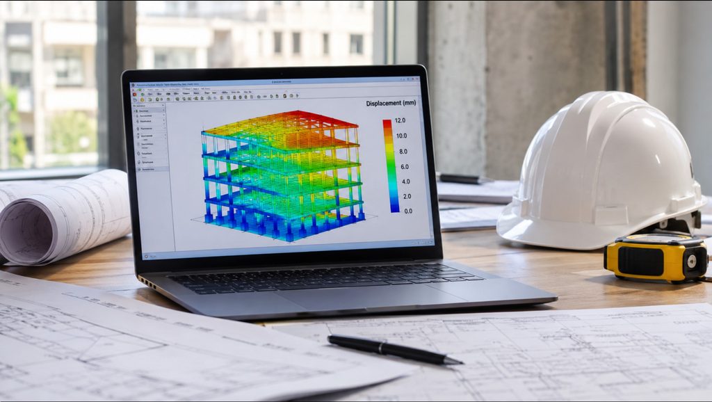
A model can converge successfully and still produce unrealistic results. It may satisfy numerical checks while misrepresenting the actual load path or structural stiffness.
Structural analysis software has transformed how engineers analyse and design buildings, bridges and other structures. Modern applications can analyse complex structural systems within minutes. They can also produce detailed results that would require considerable manual effort. However, computational accuracy does not necessarily guarantee structural accuracy.
Every structural model is a simplified version of a physical structure. Engineers define its geometry, materials, connections, supports and loading conditions. The software uses these inputs to calculate the structural response. The accuracy of its results therefore depends heavily on the assumptions behind the model.
A model can converge successfully and still produce unrealistic results. It may satisfy numerical checks while misrepresenting the actual load path or structural stiffness. This often happens when engineers focus on the software operation rather than structural behaviour. Understanding these problems requires examining how modelling decisions influence the analysis.
1. Incorrect Structural Idealisation
Structural idealisation converts a physical structure into a mathematical system. Engineers represent members using elements such as beams, columns, plates, shells and solids. They also simplify connections, supports and material behaviour.
These simplifications are necessary because actual structures contain numerous interacting components. However, every simplification introduces assumptions that require justification.
Consider a reinforced concrete building with masonry infill walls. If the engineer excludes these walls, the model may underestimate lateral stiffness. This may be reasonable when the design intentionally ignores infill resistance. However, the actual building may experience significant interaction between masonry and the surrounding frame.
The opposite problem occurs when engineers assign structural stiffness to elements without sufficient justification. This can make the model considerably stiffer than the actual building. It may also change the distribution of lateral forces between frames and walls.
Element selection also affects the results. Beam elements represent member behaviour through simplified sectional properties. Shell elements represent plate and membrane behaviour. Solid elements provide a more detailed three-dimensional representation.
A beam element may adequately represent a conventional floor beam. However, it may not capture local stress distributions around a complex transfer region. The engineer must select elements that suit the behaviour under investigation.
The objective should not be maximum modelling complexity. It should be an idealisation that captures the structural behaviour relevant to the design problem.
2. Unrealistic Boundary Conditions
Boundary conditions determine how a structural model interacts with its supports and surrounding components. They control permitted movements and influence force transfer.
A pinned support permits rotation but restrains specified translations. A fixed support also restrains rotation. These idealisations produce different structural responses under identical loading.
The problem arises when engineers apply textbook support conditions without considering actual structural behaviour. For instance, a foundation does not automatically behave as perfectly fixed or perfectly pinned. Its rotational restraint depends on foundation dimensions, soil stiffness, embedment and surrounding ground conditions. A shallow foundation on relatively stiff soil may provide considerable rotational restraint. However, that restraint may differ significantly from an assumed fixed support.
Overestimating support stiffness can reduce predicted displacements and alter member moments. Conversely, underestimating stiffness can produce excessive movement and different force distributions.
Foundation flexibility may also redistribute forces throughout a statically indeterminate structure. Therefore consider soil-structure interaction where its influence becomes significant.
Springs can represent partial translational or rotational restraint. Their stiffness should reflect defensible engineering assumptions rather than arbitrary values.
3. Incorrect Member Connectivity and End Releases
Structural analysis depends on proper connectivity between individual elements. Members must connect at the intended locations and transfer forces through compatible degrees of freedom.
A beam may appear connected to a column on screen but remain disconnected analytically. This can happen when their nodes do not coincide or when the software does not recognise their connectivity.
The resulting model may transfer loads through unintended paths. It may also develop unexpected displacements or instability.
End releases create another important source of error. A release removes the transfer of a specified internal force or moment. Engineers use releases to represent connections that cannot reliably resist particular actions.
For example, releasing the bending moment at a beam end can represent a nominally pinned connection. However, applying that release to a genuinely moment-resisting connection changes the frame’s behaviour.
The reverse error also occurs. Failing to release a connection that behaves as pinned can introduce artificial continuity. This may attract bending moments that the actual connection cannot transfer.
Engineers should base releases on connection details and intended structural behaviour. They should also inspect the analytical model for disconnected nodes, duplicate nodes and unintended offsets.
4. Inaccurate Material and Section Properties
Material properties determine how structural elements respond to applied actions. Incorrect values can affect stiffness, deformation, internal forces and resistance checks.
For concrete structures, the elastic modulus influences calculated member stiffness. Using an unsuitable modulus can distort predicted deflections and force distribution.
Cracking introduces another important consideration. Reinforced concrete members do not maintain their full uncracked stiffness under every loading condition. Cracking reduces effective stiffness and can change the distribution of internal forces.
A model that assigns gross-section stiffness throughout may therefore overestimate the stiffness of certain members. This can influence lateral displacement, column moments and load sharing between structural components.
Steel models require equally careful input. Incorrect section dimensions affect area, inertia and torsional properties. Incorrect material grades can also produce misleading resistance checks..
5. Errors in Load Application and Distribution
Incorrect loading remains one of the most direct causes of unrealistic structural results. Even a well-connected model cannot produce reliable results from incorrect actions.
Dead loads should include structural self-weight and other permanent components. These may include floor finishes, ceilings, partitions, façade elements and permanent equipment.
Some analysis packages calculate self-weight automatically. Applying the same self-weight manually introduces double counting. Omitting the self-weight factor can create the opposite problem.
Live loads also require correct distribution. Engineers should apply loads according to the intended occupancy and applicable loading standard. They should consider pattern loading where it influences critical member forces.
Wind and seismic loading introduce additional modelling requirements. Engineers must define suitable directions, exposure conditions, mass distribution and structural parameters. Incorrect diaphragm assumptions can further distort lateral force distribution.
Load combinations require equal attention. Incorrect factors or omitted combinations may conceal critical design conditions.
A useful verification exercise involves comparing total applied vertical loads with support reactions. Significant differences may indicate omitted loads, incorrect load factors or modelling problems.
6. Inappropriate Diaphragm and Slab Assumptions
Floor systems influence how buildings distribute lateral loads between their vertical resisting elements. Their in-plane stiffness determines how effectively they transfer these forces.
A rigid diaphragm assumes that the floor experiences negligible in-plane deformation. This assumption often suits conventional reinforced concrete floors. However, large openings, irregular plans and flexible floor systems can make it unsuitable.
A semi-rigid diaphragm allows the model to account for in-plane deformation. This can produce different force distributions, particularly in irregular buildings.
The choice also affects torsional response. An overly rigid diaphragm may conceal local flexibility or distort the distribution of lateral forces. Engineers should therefore assess the actual floor configuration before selecting an assumption.
Slab modelling requires attention to thickness, connectivity and stiffness. Incorrect slab thickness changes flexural stiffness significantly. Poor connectivity may prevent the slab from transferring loads into supporting beams or walls.
Engineers should also check whether the software includes slab self-weight and load transfer correctly. Duplicate load application can produce unrealistic member forces.
7. Poor Mesh Quality and Element Discretisation
Finite element analysis divides structural components into smaller elements. The mesh determines how accurately the model represents changes in displacement and stress.
A coarse mesh may fail to capture local behaviour around openings, concentrated loads and supports. It may also produce inaccurate stress distributions in regions with significant gradients.
However, increasing the number of elements does not automatically improve accuracy. Poorly shaped elements can produce numerical errors even within a very fine mesh.
Engineers should refine the mesh around openings, re-entrant corners and concentrated load regions. They should also examine element aspect ratios and geometric distortion.
Mesh sensitivity checks provide a practical way to assess numerical accuracy. The engineer analyses the same problem using progressively refined meshes. They then compare important results, including deflections, reactions and stress distributions.
If critical results continue changing significantly, the solution may not have achieved adequate mesh convergence. The engineer should investigate before relying on those results.
Stress concentrations also require careful interpretation. An extremely high local stress may indicate a genuine structural problem. However, it may also result from mathematical singularities around idealised point supports or concentrated loads.
The engineer should determine whether the peak represents actual behaviour or a numerical artefact.
8. Ignoring Geometric Nonlinearity and Structural Instability
Linear analysis assumes a proportional relationship between applied loads and structural response. It also evaluates equilibrium using the original geometry.
These assumptions may become unsuitable when structural deformation significantly affects internal forces.
The P–Delta effect illustrates this problem. An axial force acting through a lateral displacement creates an additional bending moment. This moment can increase member deformation and further amplify internal forces.
Slender columns and tall frames require particular attention. First-order analysis may underestimate their design moments when second-order effects become significant.
Engineers should assess structural stability using the appropriate design standard. Depending on the structure, they may require second-order analysis or recognised amplification procedures.
Initial imperfections also influence stability. Real structures contain geometric deviations from their theoretical positions. These imperfections can increase bending effects, especially in slender compression members.
Ignoring them may produce an overly favourable assessment of structural stability.
9. Accepting Software Results Without Independent Verification
One of the most serious modelling problems occurs when engineers accept output without questioning its physical meaning.
A successful analysis only confirms that the software solved the mathematical problem presented. It does not confirm that the model represents the actual structure correctly.
An inspection of deformed shapes before reviewing detailed numerical output is required. A building should sway in a direction consistent with the applied lateral load. Beams should deflect according to their support conditions and loading.
Bending moment diagrams should also reflect the intended connection behaviour. A model should not produce unexpected moment releases or force discontinuities without explanation.
Support reactions provide another useful verification point. Their magnitude and direction should remain consistent with applied loading and overall equilibrium.
Engineers should compare critical members against independent calculations. Tributary area calculations can provide approximate column loads. Simple beam calculations can help verify bending moments and deflections.
For complex models, engineers may use separate models to investigate specific behaviours. However, independent software does not automatically guarantee independent verification. Both models must use defensible assumptions.
10. A Practical Approach to Model Verification
Model verification should begin before the engineer runs the analysis. It should continue throughout modelling, analysis and design.
A practical review should address the following:
Confirm model geometry against approved structural drawings.
Verify element connectivity, orientation and section properties.
Review support conditions and foundation assumptions.
Check member releases against actual connection details.
Confirm material properties and stiffness modifiers.
Verify load magnitudes, distribution and combinations.
Review diaphragm assumptions and slab connectivity.
Inspect mesh quality and sensitivity where applicable.
Check deformed shapes, reactions and internal force diagrams.
Compare critical results with independent calculations.
Engineers should also document important assumptions and modelling limitations. This makes technical reviews more effective and helps future engineers understand the analytical approach.
Conclusion
Unrealistic structural analysis results rarely arise from one isolated issue. They often reflect several interacting assumptions about geometry, stiffness, connectivity, supports and loading.
Reliable structural analysis therefore requires more than successful computation. Engineers must understand the physical structure, justify their assumptions and verify critical results independently. The quality of structural design ultimately depends on the engineering judgement behind the model.
A dedicated, passion-driven and highly skilled engineer with extensive knowledge in research, construction and structural design of civil engineering structures to several codes of practices
View all posts by Omotoriogun Victor