Selecting the most appropriate foundation type is often a very difficult undertaking in design and construction. Even, perhaps the most important part of the design process. Rightly so, it can be argued that the foundation of any structure is the most principal component of that structure. Damage to the foundation of any structure could mean damage to the entire structure, and even where correctional procedures can be undertaken, they’re often too costly to consider an option. Hence deciding the most suitable form and type of foundation must be given proper consideration at the scheme design level.
To select a foundation type requires an appraisal of some very important factors, which includes, subsoil conditions, past site usage, adjacent construction, size and scale of the proposed development, the timescale for construction and cost limitation. All of these must be considered at the level of site investigations, this has been discussed extensively in a previous article. It should be read as a prerequisite to this very article.
See: Sites Investigations in Foundation Design
Whilst site investigations tend to be more concerned with the sub-soil conditions it must be appreciated that subsoil conditions are only one factor and one part of the overall equation when it comes to selecting a foundation. Selecting the most suitable foundation type is a design process that must continually evolve as we go. All factors, especially those described in the preceding section must be continually reviewed. Hence, a foundation designer must select a foundation using a careful blend of engineering geology, soil mechanics, analysis and design, experience, logic and engineering judgement. A foundation designer must understand that sampling soils is never an accurate science and cannot be solely depended on. It is when corrected by logic and practical experience does it become an excellent guide for use in foundation design.
This post focus is on the various forms and types of foundation and the criteria for their selection. It aims to define the general terms, different functions, the materials employed and how they behave. The foundation types will be discussed under three discrete categories
- Pad/Strip Foundations
- Raft Foundations
- Piled Foundations
Pad/Strip Foundations
The pad and strip footings belong to the family of spread foundations. They are the most basic and cost-effective type of footings for any structure. Their primary purpose is to deliver and spread all loads coming from the superstructure to the ground by spreading them over a suitable area. As with all spread foundations, they are required to be very stiff, in order to be able to distribute the loads in a very uniform manner, without exceeding the permissible bearing stress.
Although the strip and pad footings have a lot in common, in terms of form, analysis and design, they’re not exactly the same, a minor distinction does exist. Whilst strip footings are mostly utilized under a system of relatively uniform point /line loads or under a wall. Pads are on the contrary used to spread loads from mostly single columns or at most two-three columns.
There are a number of different types of strip and pad footings, these are described as follows:
Masonry Strips
Talking about, pad and strip footings being the most basic type of footings, masonry strips can be likened to the most basic of the most basic foundations for masonry walls although they’re rarely used these days. Where very good quality soil exists and where raw materials for masonry construction are predominantly cheap and in abundance, they can be used.
Concrete Strips
In recent times, masonry strips have been replaced by concrete strips. Concrete strips are of two forms. The plain concrete strips and the reinforced concrete strips, the latter is often referred to as wide strip footings. In plain strip footings, the thickness is determined by the requirement for the line of dispersion to pass through the side of the footing (See figure 1).
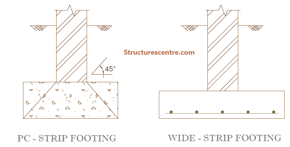
By this requirement, the width of any plain concrete strip footing is always three times the masonry wall thickness. While the strip footing thickness is the same size as the masonry wall thickness. Thus for a 230mm masonry, the footing width ideally should be 690mm while the footing thickness is 230mm.
Reinforced wide strip footings are very similar to the plain strip footing except that they’re typically reinforced with a fabric or reinforcement. This means that they can be made wider while the thickness of the footing can be drastically made thinner. Thus, it no longer relies on the approximate 45° line of load dispersion.
Generally, plain concrete strips are used. Wide strips are only employed where bad grounds with low permissible bearing stresses are encountered.
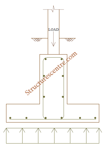
Inverted T beams Strips
Inverted T beams strip footings consist of a reinforced concrete slab with ground beams. They’re generally utilized under a system of columns carrying very high axial loads. The beam is usually required to be of sufficient cross-section to resist the induced bending moment and shear forces in the longitudinal direction. The figure shows a typical inverted T beam strip footing.
See: Designing an Inverted T-beam Foundation
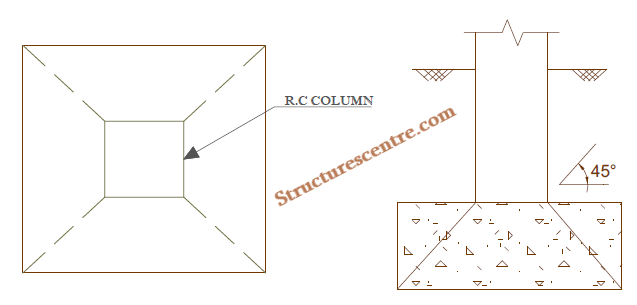
Plain Concrete Pad
Plain concrete pads, also called mass concrete pad footings are used to support point loads from columns, piers, etc. The general assumption is as mentioned previously for plain concrete strips i.e. all load are dispersed through an angle of 45°. They are particularly economical where the sides of the excavation can be used as shutter and where a suitable depth of mass concrete can be accommodated without any need for reinforcement.
Reinforced Concrete Pad
Reinforced concrete pad footings are similar to the plain concrete type. But for the same conditions can be thinner when reinforced with steel just like the wide strip footings. The reduction in thickness is made possible by the introduction of tensile reinforcement on the tensile face, thus increasing the base resistance to flexure.
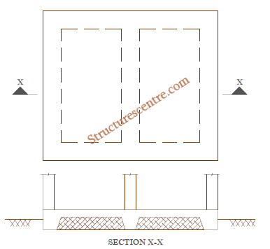
Combined/Balanced Pad
The combined/balanced pad footings (figure 5) are used where a number of point loads are required to be supported by a single pad. Particularly they’re a requirement where it’s impossible to construct single footings for individual columns without overlapping and where excessive variations in pressure could produce unacceptable differential movement.
They’re considered balanced footings where the cantilever ends of the pads are adjusted in order to allow the resultant pass through the centroid of the base. However, where there is a constraint on the geometry of the footings, the induced eccentricity is calculated and designed for accordingly.
See: Designing a Balanced Pad Foundation
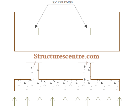
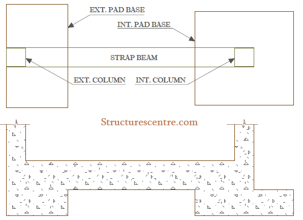
Strap Pad
The strap footings are closely related to the balanced footings. Their uses are in scenarios where the base for an external column must not project beyond a building line, either due to site constraints or property line restrictions. Strap footings consist of a strap beam linking the external column to the closest possible internal column (See figure 6). The purpose of the strap is to restrain the external base from overturning due to the induced eccentricity.
See: Designing a Strap Foundation
Cantilever Balanced Pad
This is a viable solution and alternative to the strap foundation. This consist of a ground beam cantilevering out over an isolated or combined footing and picking up the loads from external columns. Theoretically, the pad footings connecting the ground beams are designed to have a uniform bearing stress.
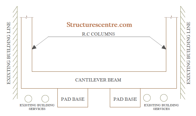
Aside site constraints and property line restrictions being the primary necessity for cantilever balanced footings, the need for cantilever arrangement can also necessitated by existing building services (See figure 7).
Raft Foundations
The second category of foundations is the raft foundations. Also referred to as surface spread foundations. They are a general requirement where normal ground bearing strata is poor or where the depth to suitable bearing soils are excessive or in rare situations where the load carrying capacity of the soil deteriorates with depth.
Thus, the motivation for raft foundations is to be spread the loads from the superstructure and sub structure over a large base area in most instances the entire building footprints thereby reducing the contact bearing stress to acceptable limits.
There are several types of raft foundation most of which are briefly described in the next section.
Nominal Crust Raft
The nominal crust raft is the simplest form of raft foundations used where ground conditions are reasonable and loadings are relatively light. It’s basically consist of a reinforced concrete flat slab with nominal thickenings around the columns and slab edges (See figure 8).
The slab acts as a surface crust to the sub strata thus evening out any location differential settlement that may result either from either variations in the applied variable actions or variations in the settlement properties of the sub-soil. The design is generally carried out either by sizing the raft from previous experience or by calculation based on assumptions.
Crust Raft
A crust raft is merely a stiffer and stronger version of a nominal crust raft. In a crust raft, the slab and thickening are combined into a total raft design. It’s typically more suited for heavier loads on soil of relatively low bearing capacity, but where dispersing the loads on the ground will control differential settlements. It’s even more attractive where these conditions occur on a level sites.
Just like the nominal raft, experience and engineering judgement will determine the sizing of the raft. However, the thickness of the raft is usually the deciding factor and this normally exceeds the nominal crust slab requirements.
Blanket Raft
The blanket raft is basically a crust raft constructed on a stone blanket which is usually built up in layers off the sub soil reduced level (See figure 9). In a blanket raft foundation, the concrete crust interact with the blanket to support and span over any localized soft spots and depressions. From all indications, this is basically a crust raft with the only distinction being the introduction of the stone blanket. This blanket use is in effectively dispersing any heavy point and edge loads that might cause any imbalance. The design of this type of foundation relies on the composite action between the crust raft and the stone blanket.
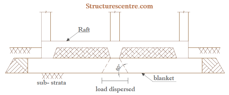
Blanket rafts are primarily used for low rise developments on very poor soils, for example in a swampy area making excavation difficult or where the soil strata varies leading to differential settlement. Generally, the motivation to use a blanket raft arises from the need to upgrade soil strata where alternative of piling, vibro-compaction or other ground improvement procedures are considered unnecessary or excessively expensive.
Slip-plane Raft
A slip plane rafts (figure 10) consist of a concrete flat slab constructed on a slip-plane layer, such as sand of known internal friction angle and shear resistance. The slip plane is constructed with sufficient thickness to ensure that a straight failure plane would occur under excessive longitudinal ground strain.
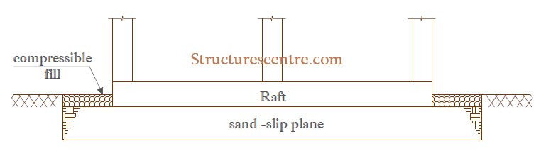
Slip plane raft is a favourite on sites involving active mining areas or where ground strains can be set up as a result of subsidence. If these strains are allowed to be transferred up into the foundation it could damage the entire structure . Hence by using a slip plane of known resistance, the maximum force which can be transferred up into the building before the plane ruptures can be estimated and the raft slab designed to resist this force in any direction it’s likely to occur.
Beam Strip Raft
The beam strip rafts consist of ground bearing down stand or upstand beams in two or more directions to support the heavy concentrated loads from the superstructure. The beams are tied together by a ground bearing slab supported on hardcore fillings on very compacted lateritic fillings (See figure 11).
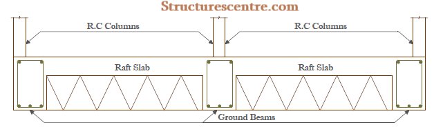
Beam strip raft are mainly used where the loads are relatively very heavy such that a stiffen beam is required on the main load lines. Tying the ground bearing slabs into the beams prevents any lateral distortions and so evens out any local differential settlements. The beam and slab are designed as separate elements which are then combined in the final design.
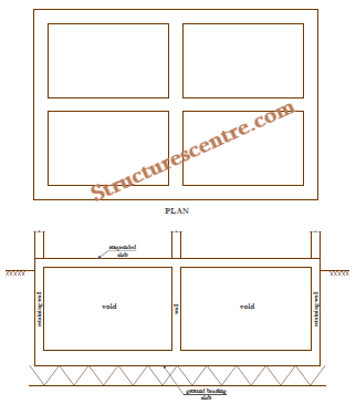
Cellular Raft
The cellular raft is an arrangement of two way interlocking foundation beams with a ground bearing slab at the underside and a suspended slab at the top surface (See figure 12). They’re typically used where a foundations is to be subjected to very heavy concentrated loads on sites with relatively very weak soils.
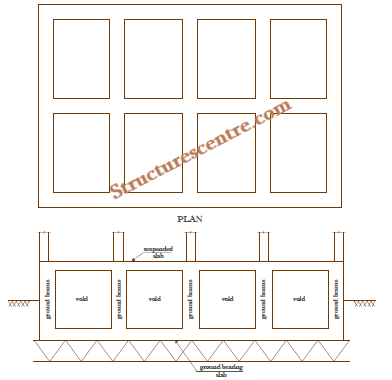
The main advantage of the cellular rafts is that, aside the fact that, the hole created by the cellular can be used for living space, storage or even service installation, the removal of overburdened soil leads to a valuable increase in bearing capacity. Its use is mostly in areas of mining activity and areas highly susceptible to seismic events. Cellular raft while being economic in these instances are one of the most expensive types of foundations, hence are seldom used.
See: Designing a Cellular Raft Foundation
Lidded Cellular Raft
The lidded cellular rafts is in fact not different from the cellular raft and is used in similar situations. The main difference, however is the use of a lighter form of upper slab designed to be separate from the main foundation (See figure 13 ).
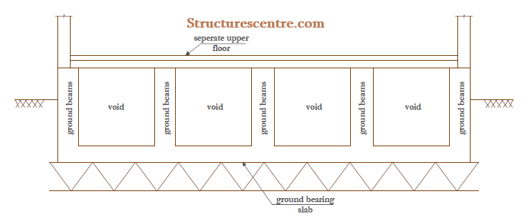
The lidded cellular raft is less stiff than the pure cellular rafts due to the light upper slab. In a pure cellular raft, the intersecting beams are treated as I and C beams. Whereas, in a lidded cellular beam the cross-section of the beams are restricted to inverted T and L beams. The advantage of the lidded cellular over the pure cellular is that the upper slab can be detailed to be re-levelled should the floor tilt or appear to be distorted.
Buoyancy Raft
A buoyancy raft is also similar to the cellular raft but with very deep and large voids (See figure 14 ). This type of rafts allows basement accommodation possible.
Buoyancy raft is used for substantially heavily loaded structures in areas of extremely low bearing capacity. Compared to the cellular rafts, they’re even more expensive to construct hence, rarely used in practice. They’re are only used where a suitable bearing soil is at great a depth to reach and where other alternatives are more expensive or not even an option.
Jacking Raft
A jacking rafts can be essentially any of the aforementioned raft foundations: Crust raft, beam strip rafts, cellular rafts est. The only difference here, is that they are designed to resist jacking forces and moment involved with the process of re-levelling. Jacking raft is the preferred choice on sites highly susceptible to excessive/unpredictable subsidence that could tilt or distort a structure to an unacceptable degree. Particularly, where re-levelling of a raft proves to be a very economic and viable foundation correction solution.
Piled Foundations
The last category of foundations falls under the purview of piling – regarded as the oldest form of foundation technique known to mankind. They are often and ultimately the last resort when all other foundations prove unsuitable and uneconomical due to very poor and stringent soil conditions or where loads coming from the superstructure are extremely heavy.
The principle behind piling is to get the superstructure loads beyond unsuitable strata of low bearing capacity to much deeper soil strata having high bearing capacity or ultimately on a rock. When piled foundations are employed, the loads are transferred to the bearing strata either through end-bearing or friction or a mixture of both. Piling has been the subject of a previous post for more extensive knowledge (see: Introduction to Piling)
Piles can be made from a variety of materials, concrete, steel, stone and timber, they all follow the same principle described above. However, we are concerned here with the types of foundation based on structural behaviour. And on this basis piled foundations can be discussed in two forms:
Pile Caps & Ground Beams
These are the simplest and common type of piled foundations used in low-medium structures. The piled foundation consists of a group of relatively small diameter piles, a pile cap or ground beam as the case may be connecting the pile group with the superstructure element (See figure 15).

In certain situations where large diameter piles are used, pile caps and ground beams are unnecessary. However, there is an exception. Aside from the fact that this constitutes a minority of the possible scenarios, there is often the need to provide lateral restraints to the top of the piles. Hence the requisite provisions of pile caps and ground beams.
See: Structural Design of Piled Foundation: Worked Example
Piled Raft
The motivation for this type of foundation arises where the conventional raft foundations cannot provide adequate support to the superstructure. It is therefore enhanced by adding piles to the schemes in what is now known as a piled raft (See figure 16).
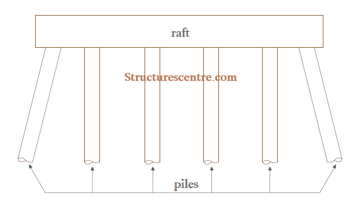
Piled raft are basically used for very large structures, as a matter of fact they’ve become a very popular choice for high-rise buildings. In piled rafts, both the raft and the piles acts together in transferring the loads to the ground. This leads to the argument of whether piled rafts should really be classified under raft or piled foundations.
Here is the deal – In most piled raft it is assumed that the upper soil strata are relatively very weak, hence a bulk of the bearing capacity in resisting loads is provided by the piles and the raft providing only nominal capacity at ultimate loading. Also, where one or more pile is defective, the raft allows load redistribution to other piles, reducing the effect of the defective piles on the performance of the overall foundation.
This article has focused extensively on the types of foundations presently available, their unique features as well as the criteria for selecting them. It is important to also state that foundation engineering is continually evolving and there is no limits to what the future holds. However, we can be sure that any new form of foundation would only be an extension on the principles of the existing foundation types described here in this article.
Thanks for reading, please share!!!
Thanks for this article
price of cialis daily – buy cheap generic cialis cialis 36
lowest price cialis 20mg – order cialis how to order cialis pills
sildenafil buy over the counter – buy sildenafil generic online buy cheap viagra canada
us pharmacy viagra – viagra from canadian pharmacy female viagra 2017
tadalafil in mexico – buy 5mg cialis cialis cost in mexico
best generic cialis online – buy cialis without prescription cialis online canada paypal
ivermectin 4000 – generic ivermectin online ivermectin 6 mg
stromectol 6 mg tablet – where can i buy oral ivermectin order stromectol
slot machine games – best online casino hard rock casino online
casino online games – empire casino online casino online slots
best non prescription ed pills – erection pills erectile dysfunction doctors near me
male ed pills – how to cure erectile dysfunction naturally and permanently ed pills
2.5 mg prednisone – deltasone generic 5mg buy prednisone online india
can you buy prednisone over the counter in canada – mail order prednisone where can you buy prednisone
cialis order online india – Cialis online cialis 5mg price in canada
ivermectin buy uk – stromectol tablet price buy ivermectin for humans uk
ivermectin 3mg pill – stromectol tablets uk buy ivermectin 3mg
which erectile dysfunction drug is best – natural pills for ed buy ed pills online usa
cheap erectile dysfunction pills online – natural pills for ed ed pills otc
Дом Гуччи 2021 смотреть онлайн
в хорошем качестве смотреть фильмы онлайн бесплатно
buy ventolin – buy ventolin ventolin cost uk
ventolin uk price – albuterol nebulizer ventolin medication
buy cytotec over the counter – cytotec 200mg pills generic cytotec online in south africa
buy cytotec uk – misoprostol where can i get cytotec in south africa
doxycycline monohydrate – doxycycline capsules price in india 20 doxycycline
buy doxycycline 11554 – doxycycline singapore pharmacy doxycycline 100mg generic
generic neurontin pill – synthroid 75 mcg price synthroid pharmacy price
neurontin cream – neurontin 100mg tab where to buy levothyroxine
http://buytadalafshop.com/ – Cialis
http://buysildenshop.com/ – buy viagra levitra alternative lavitra
where can i buy viagra in canada – viagra online canada paypal
viagra for sale in mexico – cheap generic viagra usa
Cialis Senza Ricetta Yahoo Answers
Order Nexium Samples Online
tadalafil 20mg best price – cialis 10mg online india tadalafil 20mg in india
cialis 5mg best price australia – cialis tadalafil 2.5mg cialis 10mg purchase
https://buystromectolon.com/ – ivermectin for lice
Secure Drugshop
vardenafil com – buy vardenafil laura vardenafil generic
vardenafil generic brand – cheap generic vardenafil vardenafil online bestellen
https://buysildenshop.com/ – viagra liquid
https://buypropeciaon.com/ – Propecia
stromectol for sale
costo del viagra
ivermectin cream 5% – stromectol coronavirus stromectol generic
чики сериал
stromectol 3 mg tablets price – stromectol coronavirus stromectol otc
can i buy prednisone online without prescription – buy prednisone online without prescription prednisone 200 mg daily
deltasone without rx script online – prednisone canada prednisone generic
вот
49 mg accutane – accutane cost australia buy accutane mastercard
buy accutane 40 mg online – accutans accutane pills
Propecia
Propecia
amoxicillin without a doctor’s prescription – amoxicillin 500 mg for sale amoxicillin without prescription
purchasing amoxicillin online – amoxicilin usa buy amoxicillina 500 mg online
http://buypropeciaon.com/ – Propecia
Amoxicillin Uti Children
http://buystromectolon.com/ – stromectol tablete
https://night-lady.co.il
where can i buy viagra online safely – Order viagra us best prices for viagra
where to buy generic viagra online in canada – Buy generic viagra online female viagra pill canada
Kamagra Uk Pay With Paypal
Злое
tadalafil 3mg – Price cialis tadalafil cheap uk
generic cialis compare prices – Buy cialis without prescription tadalafil 20mg daily
7683
8867
viagra generic online
cheap viagra india viagra professional northwestpharmacy.com scam ed medication ed drugs – canada buy cialis from us pharmacy buy brand viagra viagra facts about canadian drug companies buy drugs online
brand viagra online viagra drug canada generic viagra from india cialis for sale
I am curious to find out what blog platform you happen to be using? I’m experiencing some small security issues with my latest blog and I would like to find something more risk-free. Do you have any recommendations?
cialis dosage
ivermectina 6 mg – site ivermectin tablets
ivermectin 8000 mcg – stromectol ivermectin buy stromectol 2mg online
Thanks for your write-up on the travel industry. I’d also like to include that if you are one senior considering traveling, it’s absolutely crucial that you buy travel insurance for golden-agers. When traveling, elderly people are at greatest risk of having a health care emergency. Receiving the right insurance package on your age group can protect your health and provide peace of mind.
prednisone drug – 5 mg prednisone tablets where can i buy prednisone without a prescription
prednisone pack – buy prednisone online australia prednisone 10 mg coupon