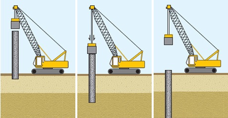
For projects that requires deep foundations, the piles would be one of the first considerations at the concept design stage. The structural designer is expected to consider during the course of the project development, the type of piling that would be required, and the proposed sizes. Generally, at this stage, the structural designer will be required to make useful inputs and guidance. While this subject is totally outside the core competence and field of responsibility of structural engineers, they must be able to give recommendations at this level based on the limited knowledge they have on the subject.
This article is a follow up to a previous post ‘Introduction to piling‘. Here, it describes how to design concrete piles according to BS-EN7 (Geotechnical design of Structures) and explicitly explains how to interpret the soil conditions from the geotechnical result of a site investigation and then design piles to match the soil investigation report.
This article, however, only deals with the design of concentrically loaded single pile or small pile groups to which the force distribution can be estimated to be uniform. The design of large pile groups is outside the scope of this article, since their behaviour is complex, and their design is a more tedious process often requiring the use of spreadsheets and finite element
Design Principles
The design of piles as explained in the preceding post is hinged on two solid principles. The friction between the soil and the pile and the end-bearing resistance offered by the soil against the tip of the pile. These two principles form the cornerstone of pile design. In some instances, only one of the two interactions can be relied on based on the result of the soil condition to which the pile will be installed. Hence the resistance of a pile is defined by its skin friction resistance and/or end-bearing resistance.
Assessing Actions
Before a pile can be designed, the actions the pile is to support must be determined. Eurocode 7, Part 1 (BS EN 1997-1:2004+A1:2013) has a very specific requirement for how pile loads are determined. There are many partial factors that need to be applied to each action. See Table in BSEN- 1997- (Geotechnical Design general rules).
Readers familiar with the design of piles to the previous codes of practice (now superseded) will see how much more complex the pile schedule table is in the Eurocode. This is because unlike previous codes of practices on piles, BS EN 1997 adopts a limit state design, hence at the ultimate limit state, each action they are subjected to has a corresponding partial factor applied to it.
Design Approach & Combinations
An added level of complexity arises from the action combinations that need to be considered in pile design. The three-letter terms are defined in BS EN 1991 (Eurocode 1) and refer to the unique load combinations structural elements are typically subjected to (Figure 1). Each combination is constructed from a series of actions that have the appropriate partial factor applied to them. With respect to pile design, the STR/GEO combinations are of primary concern and will be described in detail here.

‘A1’ and ‘A2’, ‘M1’ and ‘M2’, and ‘R1’ and ‘R4’ are terms drawn from BS EN 1997-1 that refer to sets of partial factors that need to be applied to actions, material properties of the soil and those that are applicable to resistance of the piles to applied actions.
A1 partial factors:
γG,j = 1.35 for unfavourable permanent actions and 1.0 for favourable permanent actions γQ,j = 1.5 for unfavourable variable actions and 0 for favourable variable actions.
A2 partial factors:
γG,j = 1.0 for unfavourable permanent actions and 1.0 for favourable permanent actions γQ,j = 1.3 for unfavourable variable actions and 0 for favourable variable actions.
Partial factors for key material properties of the soil into which the piles are installed are labelled as ‘M1’ and ‘M2’ (Figure 2).

Partial resistance factors are applied to the pile itself and take into account its composition and installation. For Set ‘R1’ all the relevant factors have a value of 1.0 for bored piles. For Set R4 they are as stated in Figure 3.

Finally, when calculating the capacity of a pile, a model factor (γR;d) is used to bring the characteristic capacities in keeping with existing UK experience in terms of reliability and settlement. Where piles are being designed solely based on soil data, the model factor is equal to 1.4. Where a representative maintained pile load test is performed on site (taken to the calculated un-factored resistance of the pile), this can be reduced to 1.2.
Detailed Design of Piles
As with the bearing capacity check for spread foundations the following expression must be satisfied for a single pile or group of piles.
{ F }_{ d }\le { R }_{ d }Where:
Fd is the applied action on the pile or group of piles Rd is the design resistance of the pile or group of piles.
The following section describes how the value of Rd is derived using the factors described in the previous section concerning partial factors.
For axially loaded piles, which this note is primarily concerned with, the variables Fd and Rd can be replaced with Fc;d and Rc;d and Ft;d and Rt;d for compression and tension piles respectively.
When considering compression piles, both end bearing and skin friction can be taken into account, provided the end bearing material has sufficient integrity to be able to resist a force at the end of the pile. These resistances are typically considered separately:
Skin friction for compression resistance pile is defined as:
{ R }_{ s;d }=\frac { { R }_{ b;k } }{ { \gamma }_{ s } } End bearing resistance is defined as :
{ R }_{ b;d }=\frac { { R }_{ b;k } }{ { \gamma }_{ b } } Where:
- Rs:k is is the characteristic skin friction resistance of the pile
- Rb:
k is the characteristic end bearing resistance of the pile.
Therefore, the value of Rt:d can be calculated as follows:
{ R }_{ t;d }=\frac { { R }_{ t;k } }{ { \gamma }_{ s;t } } The principal method of designing piles to the Eurocode is based on the characteristic soil parameters, as derived from on-site investigations. This method requires data on key variables of the soil’s properties, to which material factors are then applied. These are designated as M1 and M2 and vary depending on what action combination set is being considered.
When using this method, piles under compression are designed based on Equation 1 (skin friction) and Equation 2 (end bearing):
{ R }_{ s;k }=\int { \frac { { q }_{ s;k }{ P }_{ s }dL }{ { \gamma }_{ R;d } } } ---------(1)Where:
- qs;k is the shaft resistance based on the characteristic soil properties
- Ps is the perimeter length of the pile L is the shaft length of the pile
- dL is the equation integrated along the length of the pile
- γR;d is the model factor.
{ R }_{ b;d }=\frac { { A }_{ b }{ q }_{ b;k } }{ { \gamma }_{ R;d } } ---------(2)Where:
- Ab is the cross-sectional area at the base of the pile
- qb;k is the base resistance of the pile based on the characteristic soil properties.
By combining Eqs. 1 and 2 and applying the relevant partial factors, it is possible to calculate the compressive resistance capacity of the pile (Equation 3).
{ R }_{ c;d }=\frac { { R }_{ s;d }+{ R }_{ b;d } }{ { \gamma }_{ R;d } } ---------(3)For tension piles equation 4 & 5 apply
{ R }_{ t;k }=\int { \frac { { q }_{ t;k }{ P }_{ s }dL }{ { \gamma }_{ R;d } } } ---------(4)Where:
- qt;k is the shaft tension resistance based on the characteristic soil properties
- Ps is the perimeter length of the pile L is the shaft length of pile
- dL is the equation integrated along the length of the pile
- γR;d is the model factor.
{ R }_{ t;d }=\frac { { R }_{ t;k } }{ { \gamma }_{ s;t } }---------(5) When considering piles within different materials, the equations given in Figure 4 cross-reference soil type against the pile capacity in terms of its skin friction and end bearing. The model factor is then applied to convert these calculated values into characteristic values through Equations 6 and 7:


{ R }_{ s;k }=\frac { { R }_{ s;cal } }{ { \gamma }_{ R;d } } -----------(6){ R }_{ b;k }=\frac { { R }_{ b;cal } }{ { \gamma }_{ R;d } } -----------(7)Where:
- Rs:cal is the calculated skin friction resistance based on Table 5
- Rb:cal is the calculated end bearing resistance based on Table 5
- γR;d is the model factor of 1.4 or 1.2 as described previously
As a point of caution when considering pile foundations within highly variable strata or if there are risk of deterioration resulting in localized collapse, then specialist advice should be sort. The effect of high-water table on the soil properties must also be considered as it may have an adverse effect.
Serviceability
Piles, like other structural elements, must comply with movement criteria that are established by the design of the structure the piles are ultimately supporting. Typically, piles settle soon after their installation as they are exposed to significant permanent actions. The settlement of an isolated pile when it is subjected to all the characteristic working actions is typically between 0.5% and 1% of the diameter of the pile, or 10mm, whichever is the lesser.
Piles that are entirely reliant on the end bearing to support the actions being applied to them are much more prone to settlement than their skin-friction resistance-based counterparts. They can settle between 10% and 15% of the pile diameter and this should therefore be allowed for in substructure design with respect to vertical displacement.
Reinforced concrete piles that are cast in situ have to comply with certain criteria to determine whether they are of sufficient size and depth for the actions they are required to resist.
The reinforcement within bored piles must comply with minimum areas, which are based on the cross-section of the pile. The minimum amount of longitudinal reinforcement within a bored pile is defined within Table 3 of BS EN 1536:2010+A1:2015 (reproduced here as Figure 5). The configuration of bars can be as a minimum of four longitudinal bars that are 12mm in diameter.

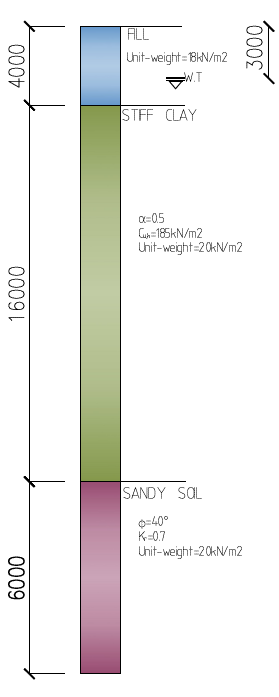
Worked Example
A concrete column (500mm x 500mm) in a building to be built on a landfill and located in Abuja, Nigeria is to be supported with 500mm diameter triple-pile, from grade C40/45 concrete to resist a compressive action consisting of 3225kN permanent actions and 1725kN Variable actions at the serviceability limit state. An intrusive soil investigation was carried out revealing the soil profile and the shear strength of all strata as shown in figure 6. Check that the proposed size of the pile is satisfactory to support these actions, using BS EN 1997-1:2004+A1:2013.
N
Actions
{ \gamma }_{ g }=1.00\quad ;\quad { \gamma }_{ q }=1.3\\ \\ Permanent\quad actions =1.0\times 3225=3225kN\\ \\ Variable\quad actions =1.3\times 1725=2243kN\\ \\ Ultimate\quad Load =3225+2243=\quad 5468kN\\ \\ Material Properties
M1\quad Values\\ Clay:\quad { C }_{ u;k }=185\times 1.0=185{ kN/m }^{ 2 }\\ Sandy-Gravel: { N }_{ q }=27\times 1.0=27{ kN/m }^{ 2 }\\ \quad \qquad \qquad \qquad \qquad { \phi }=40\times 1.0=40^{ \circ }\\ \\ The value of Nq is taken from ( IstructE manual for geotechnical design to Eurocode 7 /https://structurescentre.com/screenshot-130/
Skin Friction Resistance
Clay\quad =\quad (\pi dL)\alpha { C }_{ u;k }\\ \quad \quad { R }_{ s;k2 }\quad =\quad \pi \times 0.5\times 16\times 0.5\times 185\\ \qquad \quad \quad =\quad 2324.77kN\\ Sandey-Gravel\quad =\quad (\pi dL){ k }_{ s }{ \sigma }_{ v }'tan\left( { \phi }_{ c;k } \right) \\ \qquad { \sigma }_{ v }'\quad =\quad effective\quad stress\quad at\quad(2m)\\ \quad { \sigma }_{ v }\quad =\quad { (\gamma }_{ clay }-{ \gamma }_{ water }){ z }_{ 1 }+\\({ \gamma }_{ sand-gravel }-{ \gamma }_{ water })\frac { { z }_{ 2 } }{ 2 } \\ \qquad =\quad (20-9.81)16+(20-9.81)\frac { 6 }{ 2 } \\=193.61kN/{ m }^{ 2 }\\ { R }_{ s;k1 } = (\pi \times 0.5\times 6)\times 0.7\times 193.61tan40\\ \quad \quad \quad \quad =1071.7kN\\ { R }_{ s;d } =\frac { { R }_{ s;k1 }+{ R }_{ s;k2 } }{ { \gamma }_{ s } } =\frac { 2324.77+1071.7 }{ 1.6 } \\ =\quad 2122.8kN\\ \\ \quad \quad \quad \quad \quad \quad \quad \quad \quadN
End Bearing
{ R }_{ b;k }=\frac { \pi }{ 4 } ({ N }_{ q }{ \sigma ' }_{ v })\\ { N }_{ q }=27;\quad { z }_{ 1 }=3m;\quad { z }_{ 2 }={ 1m }\\{ z }_{ 3 }=16m;\quad { z }_{ 4 }=6m{ \sigma ' }_{ v }=\quad effective\quad stress\quad @\quad tip\quad of\quad pile\\ { \sigma }'_{ v\quad }=({ \gamma }_{ fill }{ z }_{ 1 })+({ \gamma }_{ fill }-{ \gamma }_{ water }){ z_{ 2 } }+\\ \qquad ({ \gamma }_{ clay }-{ \gamma }_{ water }){ z }_{ 3 }+({ \gamma }_{ sandygravel }-{ \gamma }_{ water }){ z }_{ 4 }\\ \qquad =\{ (18\times 3)+(18-9.81)1+(20-9.81)16\\+(20-9.81)6\} \\ \quad \quad \quad =\quad 286.3kN/m^{ 2 }\\ { R }_{ b;k }=\frac { \pi \times 0.5 }{ 4 } (27\times 286.3) = 3036.5kN{ R }_{ b;d = }\frac { { R }_{ b;k } }{ { \gamma }_{ b } } = \frac { 3036.5 }{ 2 } =1518.25kNPile Capacity
{ R }_{ c;d }=\frac { { R }_{ s;d }+{ R }_{ b;d } }{ { \gamma }_{ R;d } } \quad =\frac { 2122.8+1518.25 }{ 1.4 } \\ \quad \quad \quad \quad \quad \quad =\quad 2600.75kN/pile\\ for\quad triple\quad pile\quad =\quad 2600.75\times 3\\ \qquad \qquad \qquad \qquad \quad \quad =\quad 7802kN\\ unity\quad check\quad =\quad \frac { 5468 }{ 7802 } =0.7\\ \\Verify Capacity of Concrete to Pile
There’s a requirement for the compressive capacity of the pile to be limited to 25% of the characteristics compressive strength of the concrete at 28 days
25% of the compressive strength off the piles is:
\\ (40\times \frac { \pi \times { 500 }^{ 2 } }{ 4 } \times 0.25\times 3)= 5893kN\\ 5468kN<5893kN\quad (ok)\\ \quad \quad \quad \quad \quad \quad \quad \quad \quad See: Site Investigations in Foundation Design
The structural design of the piles is the same as for an axially-loaded stocky column. For most piles minimum area of reinforcement according to Table 5 governs.
Further Reading & References
Institution of Civil Engineers (2016) ICE Specification for piling and embedded retaining walls (3rd ed.), London: ICE Publishing
Institution of Structural Engineers (2013) Manual for the geotechnical design of structures to Eurocode 7, London: IStructE Ltd
Knappett J.A. and Craig R.F. (2012) Craig’s soil mechanics (8th ed.), Abingdon: Spon Press
Thank You!!!