Bracing layout has a major influence on the stability and behaviour of steel buildings. The position of the braced bays affects lateral stiffness, torsional response, diaphragm forces, load paths and foundation reactions
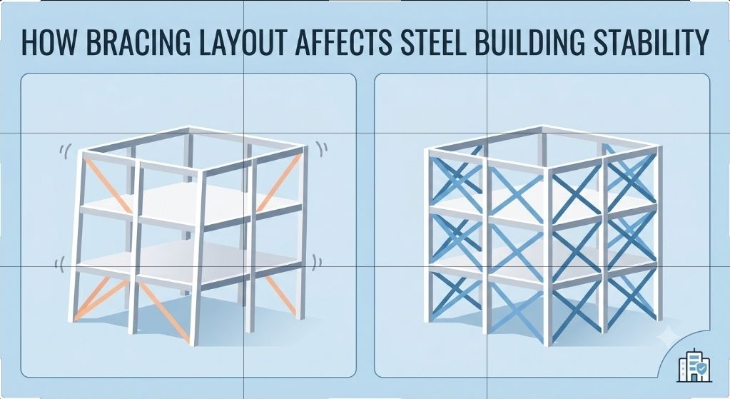
Steel buildings rely on an effective stability system to resist lateral loads and control movement. While the strength of individual bracing members matters, their location within the building can be just as important.
A building may contain adequately sized braces and still perform poorly if those braces are badly positioned. Their arrangement affects the way lateral forces travel through the floors, how the building responds to torsion, and how forces eventually reach the foundations.
For this reason, bracing layout should be considered as part of the overall structural system. Engineers need to consider building geometry, floor diaphragms, stiffness distribution, architectural requirements, load paths and construction-stage stability when deciding where bracing should be placed.
What Is a Bracing Layout?
A bracing layout describes the position and arrangement of braced bays within a steel building.
When wind or another horizontal load acts on a building, the floor and roof systems transfer the load to the vertical stability system. Braced frames then carry these forces through the columns and foundations.
The effectiveness of this load path depends partly on the location of the braced bays.
Two buildings can have the same number of braces but behave differently because their braces occupy different locations. One arrangement may distribute lateral forces efficiently, while another may create significant torsion or excessive forces in particular parts of the structure.
The engineer must therefore consider the bracing system as a complete arrangement rather than simply checking individual braces.
Why Bracing Position Matters
Bracing provides lateral resistance, but it also introduces stiffness into particular parts of the building.
If most of the bracing sits on one side of a building, that side becomes considerably stiffer than the other side. Under lateral loading, the building may then translate and rotate at the same time.
This torsional response can increase movement and force in some parts of the structure.
A more balanced arrangement generally produces more predictable behaviour. However, perfect symmetry is not always possible. Architectural openings, staircases, lifts, services and irregular floor plans often restrict where engineers can place bracing.
The objective is therefore not necessarily perfect symmetry. It is to achieve an appropriate distribution of strength and stiffness.
Bracing Layout and Torsion
Torsion becomes particularly important when the centre of stiffness does not align with the centre through which lateral loads effectively act.
Consider a rectangular steel building with bracing provided only along one elevation. The bracing may have enough capacity to resist the calculated wind load, but its position can cause the building to twist.
Providing resistance at more than one location can improve the overall response.
For example, braced bays on opposite sides of a building can provide a wider lever arm for resisting rotation. Side bracing can also help distribute lateral resistance throughout the floor plan.
The final arrangement depends on the building geometry and the relative stiffness of the different structural systems.
Creating a Clear Load Path
A good bracing arrangement should provide a clear route for lateral forces.
Wind acting on the building envelope transfers forces to the floor and roof systems. These systems then transfer the forces to the vertical braced frames, which carry them towards the foundations.
Problems can arise when the bracing arrangement contains unnecessary offsets or discontinuities.
If a braced bay terminates at one level and the system above does not continue directly to the foundations, beams or other structural members may have to transfer the forces.
Those members can then experience significant forces that would not occur in a continuous bracing system.
Engineers should therefore identify the complete load path before finalising the bracing layout.
Bracing and Floor Diaphragms
The vertical bracing system depends on the floor and roof systems to transfer horizontal forces.
A concrete composite floor, for example, can provide diaphragm action and distribute lateral loads to the braced bays. The connections between the floor system and the stability elements must also be capable of transferring the required forces.
Moving a braced bay can therefore change the forces within the floor diaphragm.
If bracing is concentrated at one end of a long building, the floor may have to transfer lateral forces over a considerable distance before they reach the stability system.
This makes diaphragm behaviour an important consideration when deciding the location of braced bays.
Bracing Along Long Buildings
The arrangement becomes particularly important in long steel buildings.
Providing only one braced bay at one end can create long horizontal load-transfer paths. Additional braced bays can distribute the lateral resistance and reduce the distance over which floor and roof systems have to transfer forces.
This principle is common in industrial and portal-frame buildings, where selected braced bays provide longitudinal stability.
The number and location of these bays should reflect the building’s geometry, loading and structural arrangement rather than follow a fixed rule.
Bracing and Architectural Openings
Architecture often controls where bracing can be placed.
Large entrances, windows and open façades can prevent engineers from using conventional cross-bracing in certain bays. Staircases, lifts and services can create similar restrictions.
Alternative arrangements such as single diagonals, chevron bracing or combinations of bracing and moment-resisting frames may provide solutions.
The most efficient structural arrangement is therefore not always the most practical one.
Good structural design involves finding a stability system that satisfies both engineering and architectural requirements.
Avoiding Bracing Discontinuity
Bracing should ideally provide a continuous and understandable load path from the upper levels to the foundations.
A change in bracing position between floors can introduce transfer forces into beams or other structural members.
This does not mean that bracing must always remain in exactly the same position. Changes may be necessary because of entrances, changes in floor use or architectural requirements.
However, whenever the bracing system changes, the engineer should explicitly design the transfer mechanism.
The forces should not be allowed to find an unintended load path through elements that were not designed for them.
Effect on Foundations
The influence of bracing continues down to foundation level.
Braced frames can generate substantial axial forces in their columns. Depending on the loading direction, one side of the braced frame may experience increased compression while another may experience reduced compression or tension.
These reactions are transferred to the foundations.
If bracing is concentrated in only a few locations, the foundations beneath those locations may receive significantly different forces from the rest of the building.
The bracing arrangement can therefore influence foundation sizes, foundation types and reinforcement requirements.
A change to the bracing layout late in the design can affect both the superstructure and substructure.
Bracing and Construction Stage Stability
The completed building is not the only condition that requires consideration.
A steel frame gains stability progressively during construction. Before all beams, floors, braces and connections become effective, the partially completed structure may behave very differently from the finished building.
Temporary bracing may therefore be necessary to maintain stability during erection.
This is particularly important where the permanent bracing is installed later in the construction sequence.
Engineers should consider the construction sequence when developing the stability system rather than assuming that the completed building arrangement will automatically provide sufficient temporary stability.
A Simple Practical Example
Consider a five-storey rectangular steel office building. Large, glazed openings prevent conventional diagonal bracing along the main façade. The rear elevation has fewer openings and could accommodate several braced bays.
Placing all the bracing along the rear elevation may appear convenient. However, concentrating the stiffness on one side can increase torsional response when wind acts on the building.
The engineer could instead introduce bracing on the side elevations, use a moment-resisting frame in selected bays, or develop another arrangement that provides a more balanced stability system.
The important point is that the engineer should not select the bracing layout simply because the braces have adequate individual capacity.
The entire building must work as a system.
What Engineers Should Check
When reviewing a proposed bracing layout, engineers should consider:
- Where does the lateral load enter the structure?
- How does the floor or roof transfer the load?
- Where are the vertical stability elements located?
- Is the bracing reasonably distributed?
- Could the arrangement create significant torsion?
- Are there discontinuities requiring transfer structures?
- Can the floor diaphragm carry the required forces?
- How are bracing forces transferred into the foundations?
- Does the arrangement remain stable during construction?
These questions help reveal problems that may not appear from individual member checks.
Conclusion
Bracing layout has a major influence on the stability and behaviour of steel buildings. The position of the braced bays affects lateral stiffness, torsional response, diaphragm forces, load paths and foundation reactions. A good arrangement must provide a clear path for lateral forces while distributing stiffness appropriately throughout the building. It should also work with the architectural layout, floor system, connections and construction sequence.
The strongest bracing member cannot compensate for a poorly arranged stability system. Structural engineers must therefore design the bracing layout as part of the complete building structure. Hence, good bracing is not simply about providing enough steel. It is about placing the stability elements where they allow the entire structure to work efficiently and predictably.
Also See: Steel Bracing in Braced Multi-storey Frames
https://structurescentre.com/steel-bracing-in-braced-multi-storey-frames/
Sources & Citations
- Institution of Structural Engineers, Stability of Buildings: General Philosophy and Framed Bracing.
- Institution of Structural Engineers, Manual for the Design of Steelwork Building Structures to Eurocode 3.
- CEN, EN 1993-1-1: Eurocode 3 – Design of Steel Structures – General Rules and Rules for Buildings.
- CEN, EN 1990: Eurocode – Basis of Structural Design.
- SCI, Steel Building Design: Design Data and Guidance.
