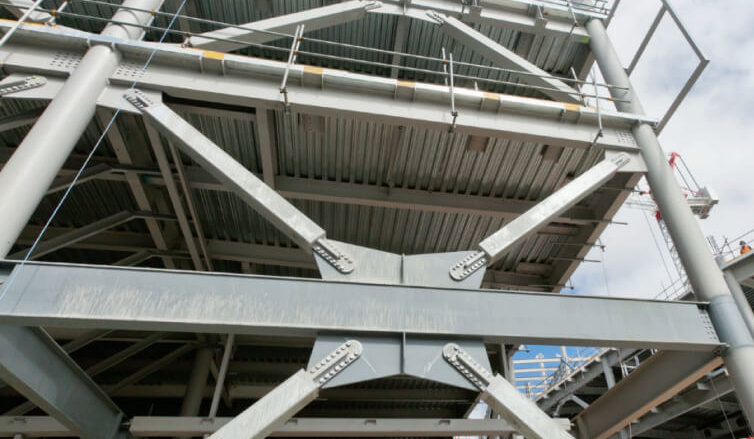
This article discusses the types of steel bracings required for ensuring lateral stability in braced multi-storey steel frames, the design considerations and the procedures required when providing them within a steel frame.
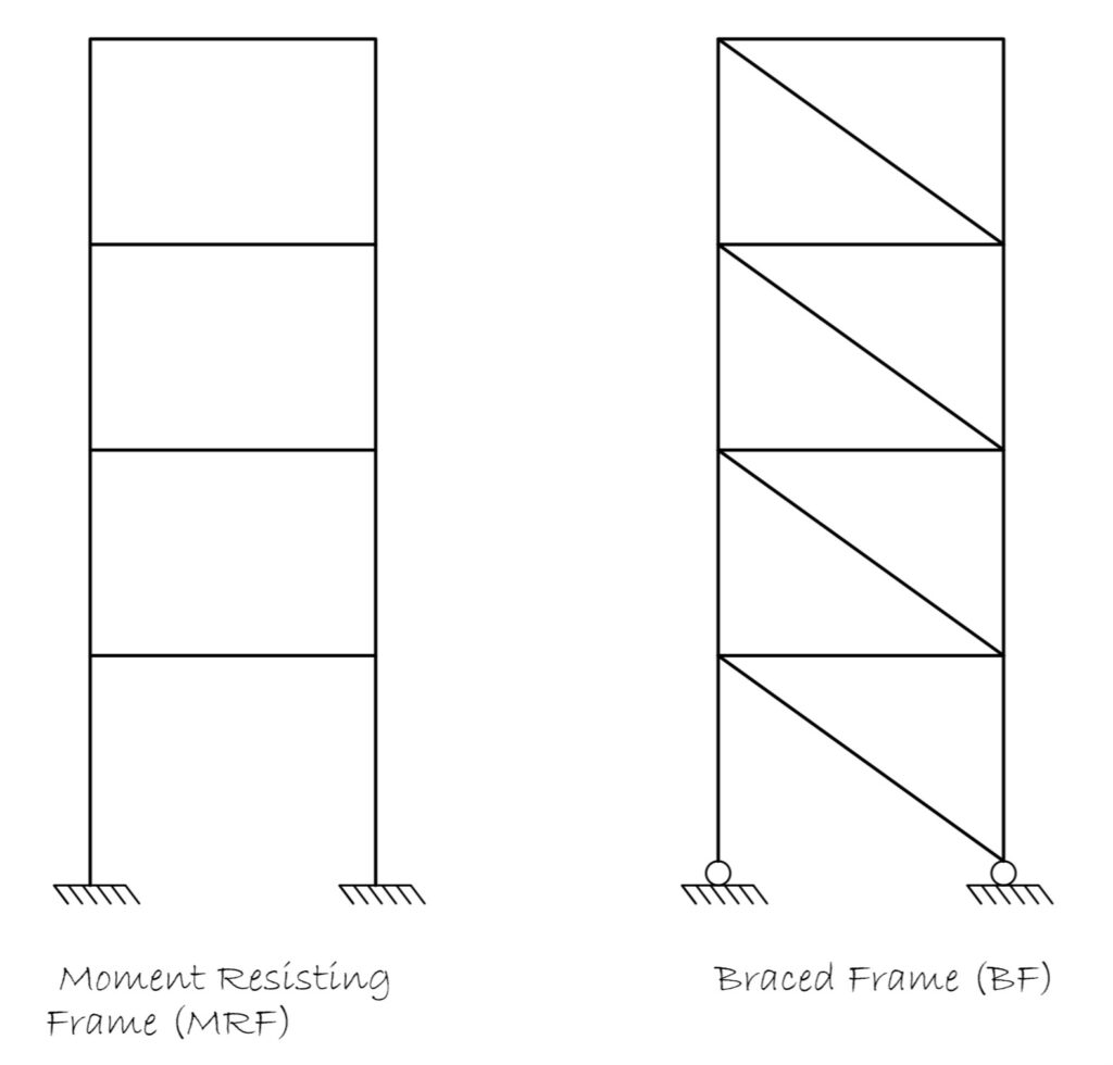
Steel frames with respect to their lateral stability can be classified into two groups; moment resisting frames and braced frames (Figure 1). In moment resisting frames, the steel connections are very stiff, they allow the transfer of bending moment to the supporting column and by virtue of this stiffness and strength of all interconnected structural elements, lateral stability is ensured. However, in braced frames, the steel connections are relatively less stiff, they are composed of simple connections, therefore there is no moment transfer between elements and lateral stability has to be provided through a different process. The process through which lateral stability is ensured in a braced steel frame is via the use of ‘steel bracings.’
This article discusses the types of steel bracings required for ensuring lateral stability in braced multi-storey steel frames, the design considerations and the procedures required when providing them within a steel frame.
A vast majority of multi-storey steel frames today, are designed as braced frames. The implication as highlighted in the opening paragraph is that the connections between beams and columns has to be nominally pinned and resistance to lateral forces is to be provided by a core, if present, or more primarily by steel bracings. A further consequence of this is that steel beams can be designed as simply supported carrying only vertical loads only and the steel columns for axial force and nominal moment arising from eccentricity between the beam-column connections, bringing a simplification to the analysis and design process.
Bracings System in Steel Frames
Steel bracings within a braced multi storey steel arrangement can be classified into two types; horizontal bracing and vertical bracing.
Horizontal Bracing
When lateral forces are applied on a braced frame, the forces are first received by the building cladding, and then to the horizontal bracing which consequently transfers it to the vertical bracing from where it reaches the foundation. The primary function of a horizontal bracing is to provide a route or load path through which all applied lateral forces would reach the foundation. Thus, horizontal bracings are provided on the horizontal plane of each floor level.
There are two forms of horizontal bracing that can be provided within a multi-storey steel braced frame. These are:
- Diaphragm
- Triangulated Bracings
Diaphragm
A diaphragm is the part of a structure that provides bracing in its plane. Usually, these are floor slabs or roof cladding, but they can also be in vertical cladding elements. In steel braced frames, diaphragms are tied back to vertical bracings of the structure that provide lateral stability. In-situ concrete slabs, metal decks, and timber floors are all excellent forms of diaphragm, albeit they may sometimes require some assessment for strength sufficiency in resisting the applied lateral loads.
Triangulated Bracing
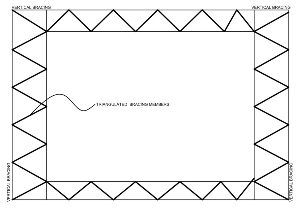
In the absence of a sufficiently stiff diaphragm, Horizontal bracing may be used, in the form of steel bracing. The bracings are arranged in the form of a modified warren truss or the modified fink truss format as shown in Figure 2. The modified fink truss is more suited for tension bracing. In both cases the floor or beams act as part of the horizontal stability system and therefore must be designed for tension or compression in addition to flexure and shear.
Vertical Bracing
Vertical bracings comprise of the diagonal bracing elements in the vertical plane of the structure provided in both orthogonal direction of the steel frame. This part of the bracing system is responsible for transferring the applied lateral forces down to the foundation. They are usually provided by bracing two lines of columns from the ground-up, just like a vertical cantilevering truss. In order for a vertical bracing to be effective, it must be provided at each floor level, throughout the entire height of the steel frame.
Just like concrete cores, it is always desired to ensure that the disposition of vertical steel bracings within a steel frame is symmetrical. This ensures that the center of stiffness of the steel frame coincides with the point of application of lateral loads, thus it can be conveniently assumed that all lateral forces are shared equally between the bracing system in the orthogonal directions. Where a symmetrical arrangement is impossible, equal sharing of lateral forces cannot be assumed and there would be introduction of torsional effects.
There are several forms of vertical bracing available based on arrangement of the bracing elements. These are listed and briefly explained in the following sections.
- Single Diagonal Bracing
- X Bracing
- Chevron Bracing
Single Diagonal Bracing
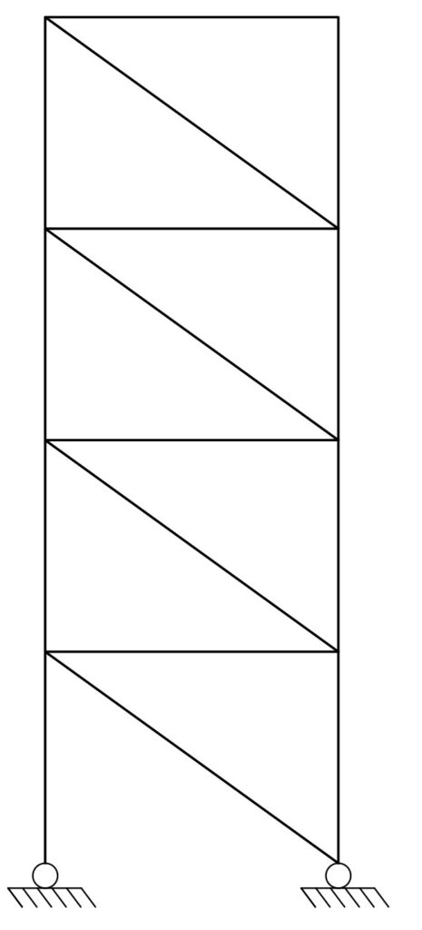
Single diagonal bracing (Figure 3) is the simplest form of vertical bracing. It is created by the introduction of a diagonal steel members between two lines of column, thereby forming a vertical truss. In the single diagonal steel bracing system, the diagonal members are either in compression or tension as the case may be.
Single diagonal bracings can be considered to be relatively economical when compared to others, since they utilize a single diagonal member. However, because some members have to be designed for compression, buckling invariably leads to an increase in member sizing. Whether this increase in member sizing can be justified against the reduction in member quantity can only be answered through design.
X Bracing
The cross or X bracing utilizes two diagonal members intersecting each other (Figure 4). In an X bracing, one of the members act as a redundant member, leaving the other member to be designed for tension only. Regardless of the direction of loading, an X brace would only resist tension. The implication, therefore, is that relative to the single diagonals, an X brace might offer some reduced member size against compression members and in favour of economy.
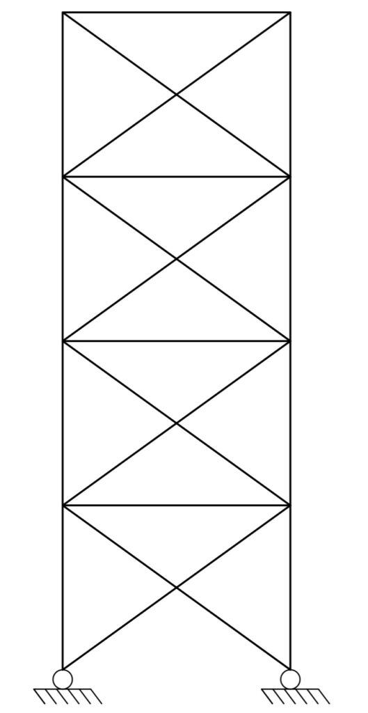
However, with regard to aesthetics, cross bracing might be undesirable as they frequently interrupt the position of openings such as windows and doors in the façade.
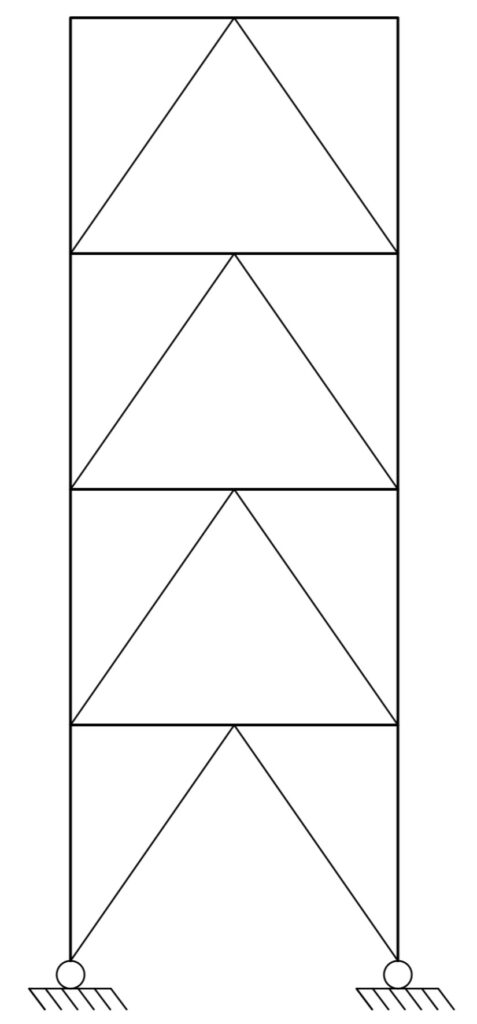
Chevron Bracing
A chevron bracing consists of diagonals members intersecting at the middle of a horizontal member to form a V shape (see Figure 5). Chevron bracings are known to offer very good elastic stiffness and strength. Unlike the X bracing, Chevron bracings are architecturally functional because they allow for openings within the braced frame.
Designing a Bracing System
For most braced frames, the floor system is usually sufficient to act as a diaphragm without the need for additional horizontal bracing, hence this article will focus only on the design of vertical bracing element. The design of a vertical bracing has to consider the following.
- Wind Action
- Equivalent Horizontal Forces (EHF)
- Frame Stability
Wind Action
The primary lateral load on the bracing system comes from wind. Wind action can be readily derived using the recommendations of BS EN 1991 (part 4). The derived wind actions are considered in combination to other actions. Typically, the load combination where wind is considered as the leading variable action would produce more onerous analysis result in the design of a bracing system.
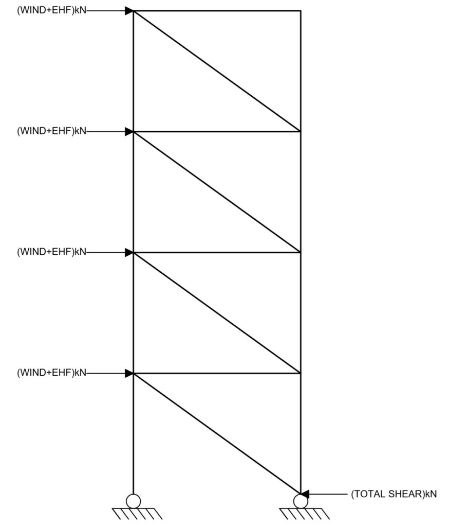
To apply wind pressure on a bracing system, the wind pressure is first converted to a force which is shared amongst the braced bays resisting the wind. And then for each bracing system, the wind force would be applied at each floor level, by proportioning the force based on story height, see Figure 6.
Equivalent Horizontal Forces
BS EN 1993-1-1 requires for global imperfections to be considered in the design of vertical steel bracings. This global imperfection can be considered through the application of some equivalent horizontal forces as it’s much easier and practical to introduce EHF’s than to introduce geometric imperfection into the model.
Equivalent horizontal forces, according to section 5.3.2(7) have the design value of ΦNEd. The procedure for determining the value of the EHF has already been detailed in a previous article. See Application of Notional Loads on Structures.
Frame Stability
The sensitivity of the vertical bracing to sway must also be checked. Where the frame is ‘sway sensitive,’ the effects of the deformed geometry on the structure needs to be allowed for within the analysis. This can be achieved through an amplifying factor as provided in 5.2.2.(2)B of BS EN 1993-1-1 or through a full blown second order analysis.
The procedure for determining the sway sensitivity of frames has also been expatiated in a previous article (See: Assessing the Stability of Frames).
Steps in Designing a Bracing System
Prior to the design of a bracing system, the designer has to Verify the reliability of the floor type in acting as a rigid diaphragm. Where there is the presence of an in-situ concrete slab, metal steel deck or timber floor, this can usually be assumed to satisfy the horizontal bracing requirement. In the absence of a rigid diaphragm, triangulated steel bracing must be provided in the floor plane.
Secondly, vertical bracings should be disposition within the structure towards avoiding torsional stresses. This can be achieved by ensuring that the center of stiffness of the steel frame, coincides as much as possible with the point of application of the lateral loads.
The following design process is recommended when designing a bracing system within a braced multi-storey steel frame.
- Choose appropriate sizes for the steel beams and steel column.
- Estimate the external lateral load from wind and the equivalent horizontal forces EHF, sharing this appropriately between the bracing system in the direction of the applied loads. For each vertical bracing, proportion the lateral load floor by floor, based on storey height.
- Calculate the total shear at the base of the braced frame and analyse the system as a cantilever truss.
- Size the bracing elements by designing members in compression for axial compression (See: Design of Steel Elements in Axial Compression to EC3) and members in tension for tension (See: Design of Steel Elements in Tension to EC3).
- Assess the frame stability, in terms of the parameter αcr, using the combination of the wind load and EHF as the lateral forces on the frame, in conjunction with the vertical loads.
- Where the frame is found to be sensitive to sway, i.e., if αcr < 10 an amplification factor is to be determined and all lateral forces are to be amplified. Thus, the bracing elements would be rechecked or even resized for the amplified forces.
Worked Example
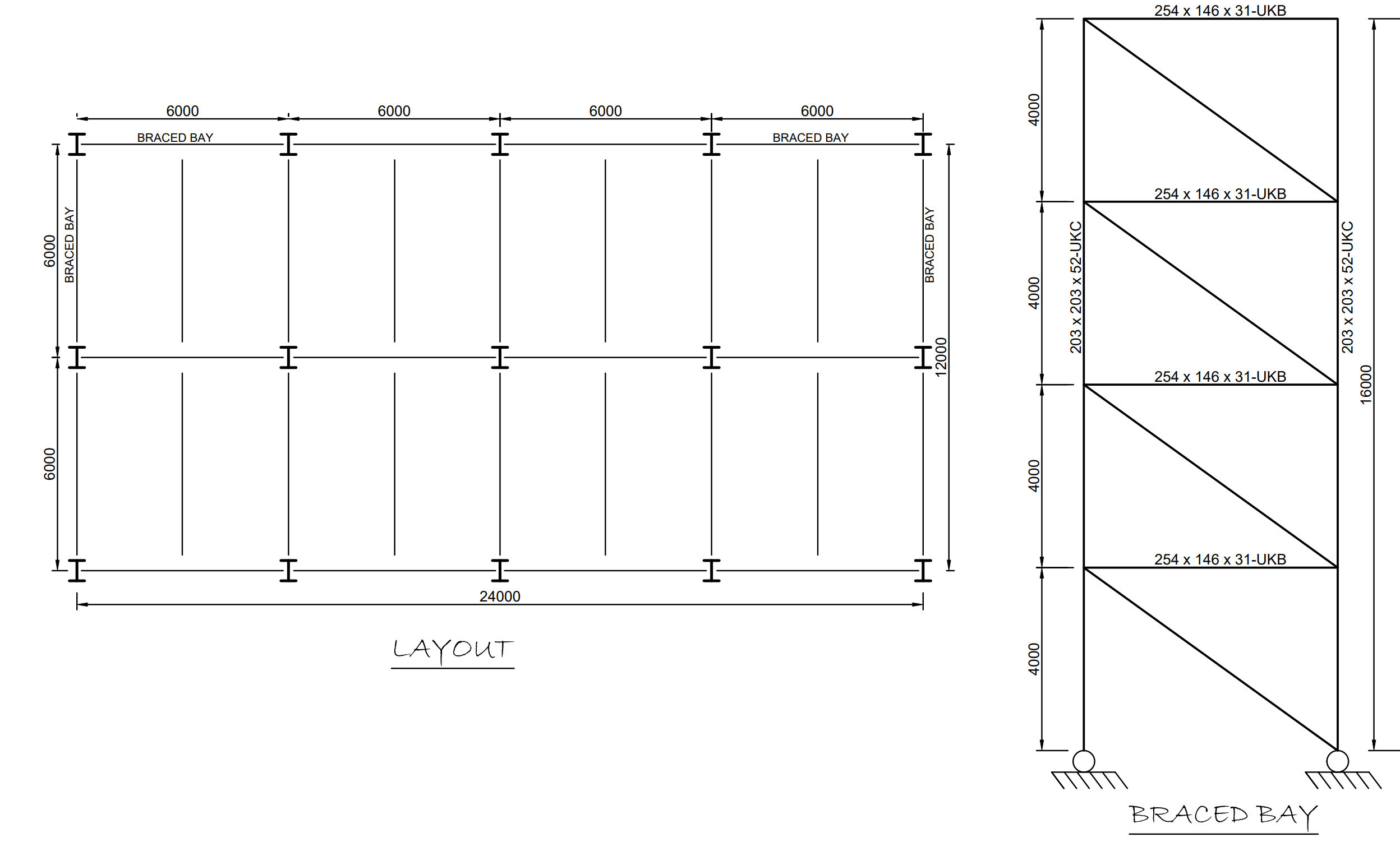
The figure shown below is the typical floor plan and braced frame of a 4-storey of an office building. The building is composed of a composite metal steel deck and steel beams with steel columns designed in simple construction. Lateral stability is being ensured in each direction through the disposition of two 6.0m braced bays each. Assuming the composite steel deck is sufficient to act as a rigid diaphragm, using the data provided in Table 1, size the vertical bracings at base level only, when wind is acting on the 24m side of the building.
| Roof permanent actions | 1.5kN/m2 |
| Roof imposed actions | 0.6 kN/m2 |
| Floors permanent action | 4.5kN/m2 |
| Floors imposed actions | 3.0kN/m2 |
| Wind Pressure | 1.8kN/m2 |
| Steel | S275 |
Design Value of Actions
When two or more variable actions are acting simultaneously, BS EN 1990 states that one of them must be considered to be the leading variable action at a time while others are the accompanying variable actions. In this case we have two variable actions, the imposed loadings and wind, hence two loading combination should be considered -one in which the floor-imposed loading is taken as the leading variable action while wind is the accompanying action and vice versa.
However, for most typical braced bays, the loading combination where wind is the leading variable would usually produce more unfavourable results in the brace member, hence we can restrict ourselves to these alone. From Eqn. 6.10 of BS EN 1990, the design value of applied actions is given as:
{ n }_{ s }=1.35{ g }_{ k }+{ 1.5\psi }_{ o }{ q }_{ k }+1.5{ w }_{ k }Vertical Loads
@ Roof Level
\quad { n }_{ s,roof }\quad =1.35{ g }_{ k }+1.5{ \psi }_{ o }{ q }_{ k }\\ =\left( 1.35\times 1.5 \right) +\left( 1.5\times 0.5\times 0.6 \right) \\=2.48kN/{ m }^{ 2 }{ V }_{ Ed,roof }={ n }_{ s,roof }{ A }_{ ref }=2.48\times \left( 12\times 24 \right)\\ =714.2kN@ Floor Level
\quad { n }_{ s,roof }\quad =1.35{ g }_{ k }+1.5{ \psi }_{ o }{ q }_{ k }\\ =\left( 1.35\times 4.5 \right) +\left( 1.5\times 0.7\times 3.0 \right) \\=9.23kN/{ m }^{ 2 }{ V }_{ Ed,roof }={ n }_{ s,roof }{ A }_{ ref }=9.23\times \left( 12\times 24 \right) \\=2658.2kNWind Loads
{ w }_{ d }=1.5{ w }_{ k }=\left( 1.5\times 1.8 \right) \\=2.7kN/{ m }^{ 2 }The total wind force acting parallel to the length of the building:
{ F }_{ d }={ w }_{ d }{ A }_{ ref }=2.7\times \left( 24\times 16 \right) \\=1036.8kNThis wind force would be shared between the braced bays, since there are two braced bays, wind force carried by each braced bay is one-half the total value = (1036.8/2 = 518.4kN).
The wind force can be distributed as point loads at floor levels in proportion to the storey height. In this case:
@Roof=\frac { 2 }{ 16 } \times 518.4=64.8kN@Floors=\frac { 4 }{ 16 } \times 518.4=129.6kN@Base=\frac { 2 }{ 16 } \times 518.4=64.8kNAt base level, the wind force can be assumed to be carried in shear by the ground floor slab, hence its value is ignored in the frame analysis.
Equivalent Horizontal Forces
Equivalent horizontal forces are determined using the equation (Φ0αhαmVEd) for simplicity, the reduction factors are going to be ignored. This is conservative.
Equivalent horizontal forces shared between each braced bay:
@Roof=\frac { 1 }{ 200 } \times 714.2\times 0.5=1.79kN@Floors=\frac { 1 }{ 200 } \times 2658.2\times 0.5=6.65kNAnalysis of Braced Bay
A computer analysis of the bracing system can be performed to obtain the member forces. Alternatively, hand calculations can be carried out to find the member forces by analyzing the braced bay as a cantilever truss. However, since we are interested in sizing the bracing at base level only, simply resolving forces horizontally at ground level is sufficient to calculate the force in the lowest (most highly loaded) bracing member, as shown in Figure 8.
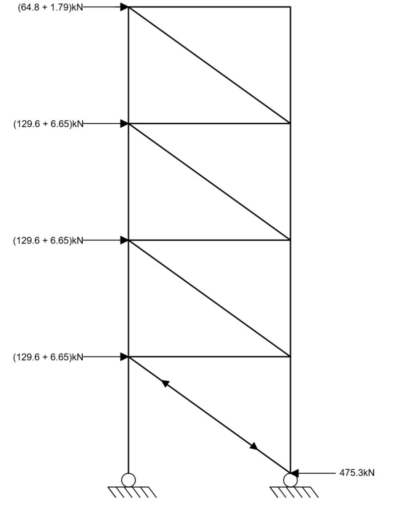
Design value of base shear = 64.8+(3×129.6) + 1.79+(3×6.65) = 475.3kN
Resolving the forces into components, the axial force in the bracing member at base level is given as:
{ N }_{ Ed }=\frac { 475.3 }{ cos33.7 } =571.3kN\left( c \right) Member Verification
From the analysis, the axial force in the bracing member is compressive, thus ordinarily this member ought to be designed for compression only, however, when wind is applied in the opposite direction, the bracing member considered above will be loaded in tension. Thus, the bracing member will be designed to withstand both tensile and compressive forces of the same magnitude.
Try 168.3 x 12.5mm CHS – Section
Properties:
Depth, h=168mm; Thickness, t= 12.5mm; Radius of gyration about major & major axis iyy = iz=5.53cm; Area of section A = 61.2cm2
Tensile resistance
verify\quad \frac { { N }_{ Ed } }{ { N }_{ t,Rd } } \le 1.0{ N }_{ t,Rd }=\frac { A{ f }_{ y } }{ { \gamma }_{ M0 } } =\frac { 6120\times 275 }{ 1.0 } =1683kN\frac { { N }_{ Ed } }{ { N }_{ t,Rd } } =\frac { 571.3 }{ 1683 } =0.34<1\quad o.kFlexural buckling resistance
For design against compression, the flexural buckling resistance controls.
verify\quad \frac { { N }_{ Ed } }{ { N }_{ b,Rd } } \le 1.0Assuming no intermediate restraint, the effective length of the brace member is taken as the actual length.
{ l }_{ cr }=\sqrt { { 4000 }^{ 2 }+{ 6000 }^{ 2 } } =7211mmFor hot finished CHS section, buckling curve a applies, hence α =0.21
\lambda =\frac { { l }_{ cr } }{ i } \cdot \frac { 1 }{ 93.9\varepsilon } =\frac { 7211 }{ 55.3 } \frac { 1 }{ 86.8 } =1.5\phi =0.5\left[ 1+\alpha \left( \lambda -0.2 \right) +{ \lambda }^{ 2 } \right] \\ =0.5\left[ 1+0.21\left( 1.5-0.2 \right) +{ 1.5 }^{ 2 } \right] =1.76\chi =\frac { 1 }{ \phi +\sqrt { { \phi }^{ 2 }-{ \lambda }^{ 2 } } } =\frac { 1 }{ 1.76+\sqrt { 1.76-{ 1.5 }^{ 2 } } } =0.37{ N }_{ b,Rd }=\chi \frac { A{ f }_{ y } }{ { \gamma }_{ M1 } } =0.37\times \frac { 6120\times 275 }{ 1.0 } =622.7kN\frac { { N }_{ Ed } }{ { N }_{ b,Rd } } =\frac { 571.3 }{ 622.7 } =0.92<1\quad o.kUse a 168.3 x 12.5 Circular Hollow Section
Frame Stability
Finally, having sized the brace section, a check for the frame susceptibility to second order effect must be carried out. If the frame is found to be sensitive to sway, the bracing members have to be resized for the increased lateral forces, either through the use of amplification factors or a full blown second order analysis.
See: Design of Steel Trusses to Eurocode3
Sources & Citations
- D.G Brown., D.C Iles., E. Yandzio. Steel Building Design: Medium Rise Braced Frames in accordance with Eurocodes and the U.K National Annexes. Steel Construction Institute.
- M.E Brettle., D.G Brown. Steel Building Design: Worked examples for students In accordance with Eurocodes and the UK National Annexes. Steel Construction Institute.
- BS EN 1993: Design of steel structures – Part 1-1: General rules and rules for buildings
- U.K National Annex to BS EN 1993: Design of steel structures – Part 1-1: General rules and rules for buildings.