This article offers an extensive discussion on the analysis and design of portal frames based on the recommendations of Eurocode 3.
Steel portal frames have become one of the most popular modes of constructing single Storey, pitched roof buildings. This is due to their versatility and economy, which covers a wide range of buildings forms. They are a very efficient and economical structural solution for supporting relatively light loads, over a relatively long span, such as found in industrial buildings such as warehouses, workshops, shopping complexes, terminals etc.
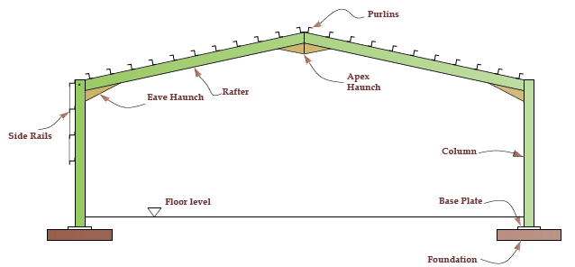
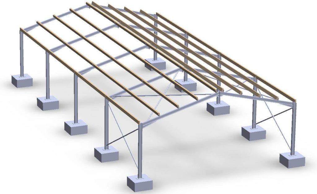
In its basic form a steel portal frame is a structure comprising of steel columns and horizontal or pitched rafters (in the form of steel beams) connected together by moment connections (See Figure 1). Portal frames are designed to be unbraced in their own plane; hence the frame relies on the moment connections which are sometimes stiffened at Eaves and Apex to form a haunch. The aim is to create a structure that is stable in its plane without a special requirement of bracing, thus providing an uninterrupted span.
Aside the asymmetric structural form that is used to mainly describe portal frames, they may also assume several forms. These variants include, crane portal frames, tied portal frames, curved rafter portal frames, propped portal frames and so on. There is a more extensive discussion on this in the earlier discussion on the subject See (Introduction to Portal Frame Structures). Here the analysis and design of portal frame is discussed.
Within the above-referenced article, the preliminary aspects of designing a portal frame structure were presented. This involved a consideration of the factors influencing the overall design of a portal frame including, clear span and height, main frames, possible position of restraints and so on. In this article only, the analysis and design aspects of a portal frame is considered. The reader is implored to read the referenced article as a precursor to this.
Actions on Portal Frame
When working to the Eurocodes, advise on the actions to be applied on a portal frame structure can be obtained from BS EN 1991 and BS EN 1990. Generally, this can be classified into permanent and variable actions.
- Permanent (Dead) Actions: The permanent actions include all dead loads applied on the portal frame, including the self-weight of the portal frame, all secondary steel work and cladding. See recommendation on values in N.A of Eurocode 1.
- Variable Actions: Variable actions include all loads applied on the truss that varies in magnitude with time. This includes, imposed loading, wind actions and snow actions. Procedure for derivation can be found in the N.A of Eurocode 1.
Method of Analysis
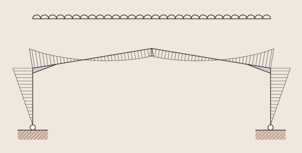
There are two methods of analyzing portal frame structures: elastic and plastic analysis. Elastic analysis of portal frame structures assumes that the frame cannot undergo permanent inelastic deformations when subject to load. When the portal frame is loaded under gravity load, the bending moment peaks at the eaves and at the hunch. At the eaves the bending moment is hogging while at the apex, the bending moment is sagging. (See Figure 2). Where a portal frame structure is restricted to elastic analysis the maximum moment at the eaves and apex are usually higher than what is otherwise obtainable when plastic analysis is carried out, hence elastic analysis often results in less economical frames.
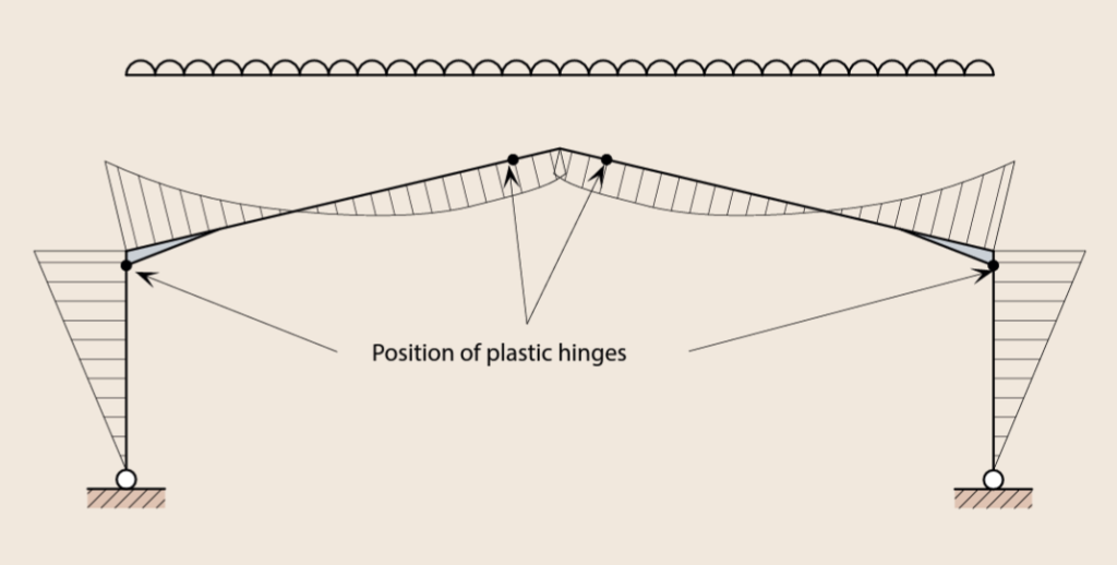
In plastic analysis, the portal frame is allowed to undergo inelastic deformations, thus allows a relatively large redistribution of bending moment throughout the frame, due to the formation of plastic hinges. These plastic hinges would often form at sections within the frame where the bending moment reaches the plastic moment resistance of the steel section (Figure 3). Thus, plastic analysis relatively results in lighter, economical portal frames.
The method of analysis to use is usually at the discretion of the designer. However, it’s worth stating that, it’s sometimes possible that even where plastic analysis is carried out on a portal frame, no plastic hinge form and thus, the frame will remain elastic.
Frame Stability & Second Order Effects
While plastic analysis strives to provide a better representation of the portal frame structure compared to elastic analysis, neither would account for the stability of the frame under load or second order effect. And we recall that portal frames are relatively slender and lighter structures prone to significant. deformations, it therefore follows that they are highly susceptible to second order effects.
BS EN 1993-1-1 Clause 5.2.2 provides a number of approaches for accounting for second order effects when constructing steel structures. BS EN 1993-1-1 Clause 5.2 defines the criteria that can be used to establish the relevance of second order effects in the study of steel structures. For more extensive discussion See (Assessing the Stability of Frames | Second Order Effects)
For portal frame structures, the sensitivity of a frame to second order effect is determined on the basis of αcr. The factor αcr is the ratio between the elastic critical buckling load Fcr of the structure for global instability and the applied design load FEd. Second order effects are deemed not to be significant when αcr satisfies the following:
For Elastic Analysis:
\alpha_{cr}=\frac{F_{cr}}{F_{Ed}}\ge10For Plastic Analysis:
\alpha_{cr}=\frac{F_{cr}}{F_{Ed}}\ge10Where second order effect is found to be significant, the amplification factor can be applied to the loadings or a full second order analysis of the frame can be carried out.
Member Stability
Portal frame structures are made from open steel sections that are vulnerable to lateral torsional buckling. Thus, there would often be the need to provide some form of restraints to the frames. Both the rafters and column in a portal frame must be checked and ensured to have adequate stability against buckling.
Generally, there are three types of restraints that is provided in a portal frame structure to assist with out of plane buckling. These are:
- Lateral Restraint: in the form of a purlin or side rail, and its function is to prevent lateral movement of the compression flange.
- Torsional Restraint: in the form of purlins or siderail combined with either a rafter or column stay, and its function is to prevent the rotation of the member about its longitudinal axis.
- Intermediate Restraint: can also be in the form of a purlin or side rail, but placed in the tension flange between torsional restraints when the outer flange is in tension. Intermediate restraints allow the distance between torsional restraints to be increased.
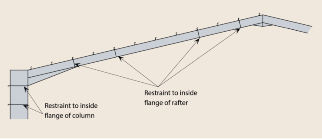
Since purlins and side rails are used to ensure member stability in portal frame structures, it follows that their position and spacings must be predetermined prior to the final design. Many times, during final design, the purlins, column, and rafter stays will have to be adjusted and readjusted to ensure stability. As a general rule, stays should be provided at the haunch and apex eaves, and the underside of the haunch (See Figure 4).
The assessment of member stability of portal frame structure is a complex subject, hence is ignored in this article, a separate article will be written in the near future to specifically address the subject.
Member Resistances
Member bending, axial and shear resistances must be verified. If the shear or axial force is high, the bending resistances is reduced so combined shear force, bending and axial force resistances need to be verified. In most typical portal frames neither the shear force nor the axial load is sufficiently high to reduce the bending resistances.
When the portal frame forms the chord of the bracing system in the plane of the roof, the axial load in the rafter may be significant, and this combination of actions should be verified.
Whilst it’s necessary to verify all sections in the portal frames, the critical points are usually the positions of maximum bending moments. This includes:
- On the column: the underside of the haunch
- In the rafter: the sharp end of the haunch
- In the rafter: at the maximum sagging location adjacent to the apex.
Generally, most portal frame structures are made up of UB-sections in recognition of the fact that the predominant action is bending and not axial. These sections would mostly have been sized from preliminary design. Hence, during the final design are mostly checked for combined axial compression and bending only.
Serviceability
BS EN 1993-1-1 does not provide serviceability limitations for steel portal frames. It is up to the design engineer to determine a suitable deflection that can be safely allowed based on the support circumstances. Such constraints must be agreed upon with the rest of the design team as well as the client. However, in portal frame structures, the practice is to keep the deflections limits less onerous. Recommendation on the limits of lateral and vertical displacement in a portal frame are based on the type of cladding material and can be found in NCCI documents. Generally lateral deflection (at top of columns can be varied between (H/(150-250), where H is the height of the column. While vertical deflection is allowed to vary between (L/200-250), where L is the span of the portal frame.
Procedure for Designing a Portal Frame
While elastic analysis is what often required to obtain the member design forces of a portal frame, plastic design is what would be carried out, as it would result in economical steel section, where the formation of plastic hinges in the frame can be mobilized. The procedure for plastic design follows the following sequence.
- Preliminary sizing of the portal frame rafters, and column based on gravity loading alone.
- Check on frame stability and second order effect, sway and snap through stability considering the gravity forces in combination with lateral forces including Notional Loading.
- Check on serviceability – deflection.
- Verify position of plastic hinges and frame resistances
- Verify member resistances and stability of columns and rafters.
Sizing a Portal Frame
- Calculate the span/height to eaves ratio = L/h
- Calculate the rise/span ratio = r/L
- Calculate the total design load FL on the frame considering gravity loadings only and then calculate FL2, where F is the load per unit length on plan of span L (e.g. F = where F is the unit load/length )
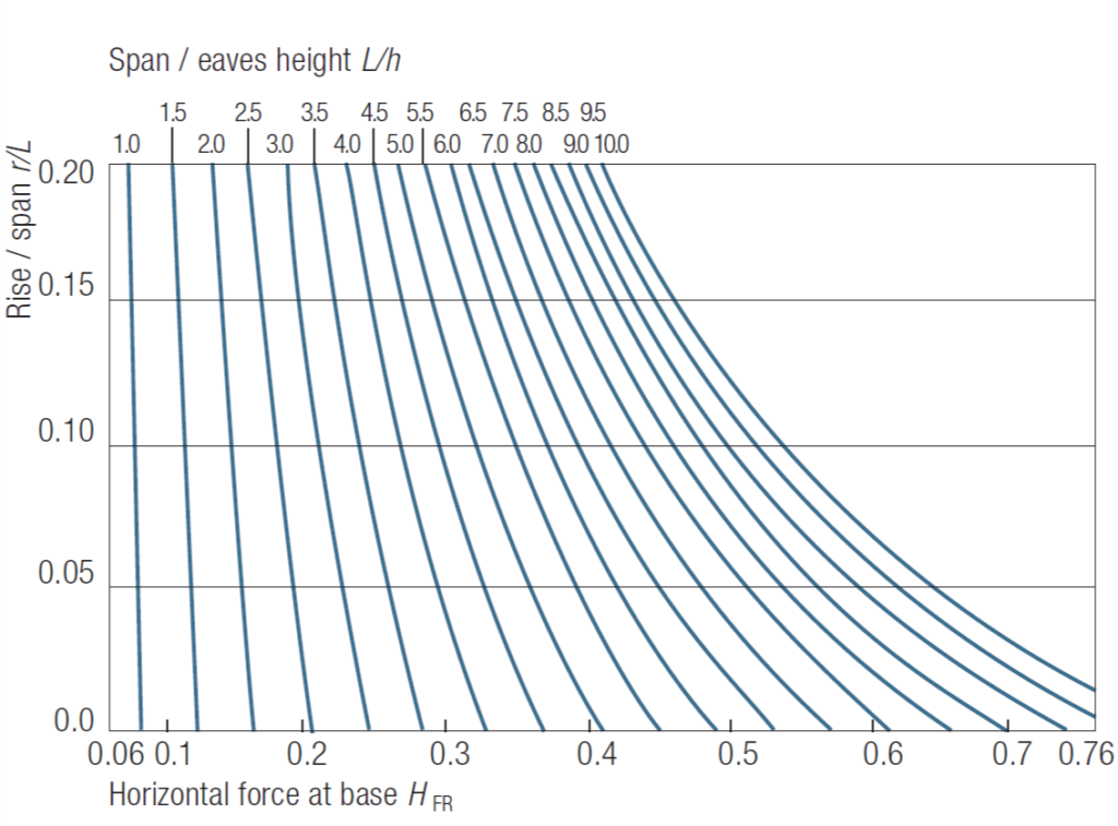
- From Figure 5 obtain the horizontal force ratio HFR at the base from
- r/L and L/h
- Calculate the horizontal force at base of span H = HFR FL
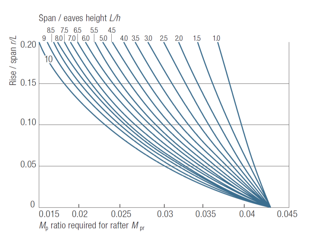
- From Figure 6 obtain the rafter Mp ratio Mpr from r/L and L/h
- Calculate the Mp required in the rafter from Mp (rafter) = MprFL2
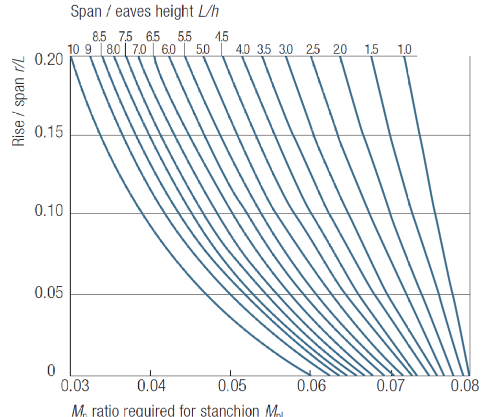
- From Figure 7 obtain the column Mp ratio Mpl from r/L and r/h
- Calculate the Mp required in the column from Mp (column) = MplFL2
- Determine the plastic moduli for the rafter Wpl,y,R and column Wpl,y,C
- Choose steel section. (Section must be class 1 in order for plastic hinge to form)
W_{pl,y,R}=\frac{M_{p.Rafter}}{f_y}\quad;\quad W_{pl,y,C}=\frac{M_{p.Col}}{f_y}Where: Wpl,y,R & Wpl,y,C are the section modulus required in the rafter and column respectively = Mp(rafter) and Mp(column) are the plastic moment of resistances while fy is the steel yield strength.
Worked Example
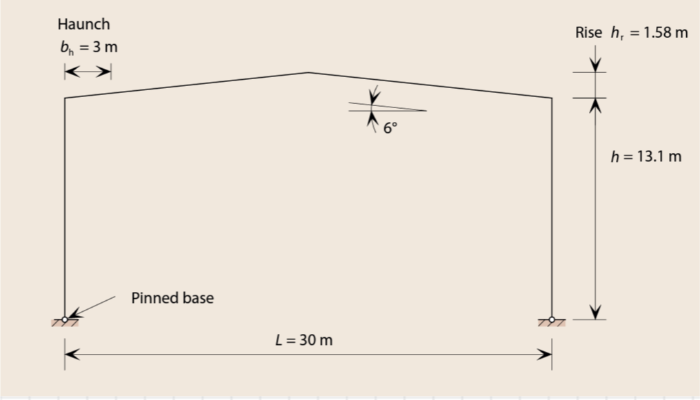
Figure 8 is the proposed portal frame section for a new warehouse building in an industrial complex. It is required to create an uninterrupted enclosed area of 30m. The nodal height of columns is 12m and this is established from a requirement of clear height. The roof pitch is 5o and the portal frames are to be spaced at 6m centers. Determine the preliminary sizes of the portal frame members, assuming that the total permanent actions due to the self-weight of the portal frame, cladding and purlins is 0.55kN/m2 imposed load is 0.6kN/m2. All members are to be in S275 steel.
Actions
Permanent Actions
g_k=0.55\times 6=3.3kN/m
Variable Actions
q_k=0.6\times 6=3.6kN/m
Design Value of Actions
F=1.35g_k+1.5q_k\\=(1.35\times3.3)+(1.5\times 3.6) =9.86kN/m
Preliminary Sizing of Members
1) Calculate the span/height to eaves ratio = L/h
\frac{L}{h}=\frac{30}{13.1}=2.32) Calculate the rise/span ratio = r/L
\frac{r}{L}=\frac{1.58}{30}=0.053) Calculate the total design load on the frame
FL=9.86\times 30=295.8kN
FL^2=9.86\times30^2=8874kN.m
4) Calculate the horizontal force at base
From figure 5; coefficient = 0.17
H_{FR}=0.17FL= 0.17\times295.8\\=50.3kN5) Determine required moment capacity of the rafter
From figure 6; coefficient = 0.0375
M_{p,rafter}=0.0375FL^2=0.0375\times8874\\=332kN.m6) Determine required moment capacity of the column
From figure 6; coefficient = 0.073
M_{p,col}=0.073FL^2=0.073\times8874\\=648kN.m7) Determine Plastic Moduli of rafter
W_{pl,y,R}=\frac{M_{p.Rafter}}{f_y}=\frac{332\times 10^6}{275}\\=1207.3cm^3Try 457x191x67-UB section (Wpl,y= 1470cm3)
8) Determine Plastic Moduli of columns
W_{pl,y,C}=\frac{M_{p.cols}}{f_y}=\frac{648\times 10^6}{275}\\=2356.4cm^3Try 457x191x133-UB section (Wpl,y= 3070cm3)
Having determined the preliminary sizes of the steel members, the detail design commences. First by analyzing the frame, considering the lateral loads from wind and EHF in combination with gravity loads. Then a check on frame stability and influence of second order effect is carried out by considering sway and snap through stability. Member stability is then considered within critical zones and sections in the column, haunch and rafter. Finally, the deflection of the frame is verified. All of these will be discussed in a later article.
Sources & Citation
- The Institution of Structural Engineers (2010) Manual for the design of steelwork building structures to Eurocode 3, London: The Institution of Structural Engineers
- The Steel Construction Institute (2012) Elastic Design of Single-Span Steel Portal Frame Buildings to Eurocode 3 (P397), Ascot, Berkshire: SCI
- The Institution of Structural Engineers (2014) Technical Guidance Note 2 (Level 2), The Structural Engineer, 92 (6), pp. 32-36