A typical portal frame structure consists of a series of frames, braced in the longitudinal direction, but unbraced in the transverse direction.
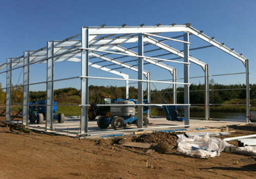
Steel portal frame is the most common, cost-effective structural solutions for single-storey buildings with gable-pitched roofs. In fact, about 50% of the steelwork in the U.K is used up in the construction of single-storey buildings, of which portal frames form the greater part. They are lightweight, efficient, and highly economical for supporting buildings envelopes, often where it is required to create a large uninterrupted column space. Thus, this type of construction is more appropriate and mostly adopted for buildings such as warehouses, shopping complexes, workshops, depots and generally industrial buildings sustaining relatively modest loads.
Portal frames are relatively flexible and highly prone to significant deformations, hence less onerous deflection limits are generally applied to them than other forms of construction. Although these deformations can be reduced by the use of larger steel sections, the cost benefits become adversative. And if deflections become so critical, for instance, from the fact that the frames are carrying heavy loads, an alternative form of construction or structural solution (such as, a girder) becomes more appropriate.
Composition of a Portal Frame Structure
A typical portal frame structure consists of a series of frames, braced in the longitudinal direction, but unbraced in the transverse direction. Each frame consists of columns and rafters which form the portal frame itself. Longitudinal bracings are provided between the portal frames and on the roof (Figure 1). The end frame is often a braced arrangement of steel columns and rafters, although a portal frame can be provided, but this is seldom the case.
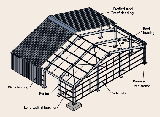
Portal frames structures, also consist of secondary steel element. This includes the side rails for supporting the external wall cladding and the purlins for the roof. The secondary steel elements are very important, because they play a critical part in restraining the portal frames (primary steel elements) against out of plane buckling.
Generally, a typical portal frame structure can be broken-down into the following composition.
Main Frame
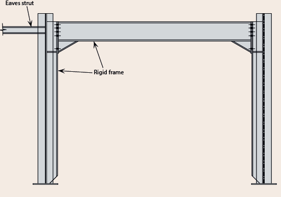
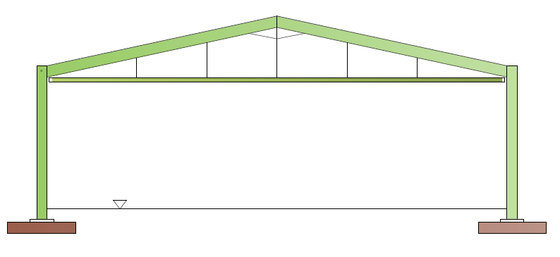
The main frame (Figure 2) consists of steel columns and steel beams which serves as the rafter. The frame is continuous with moment resisting connections. By virtue of the continuity of the frame, resistance to lateral loads and in plane stability is ensured. This means that the stability and displacement of the frame is largely dependent on the stiffness of the members. The members are formed from hot rolled steel sections, -universal steel columns for the columns and universal beams for the rafters. In addition, to enhance the resistance of the frame to flexure at the eaves and apex where the flexural moments are greatest, the frame is provided with a “haunch”.
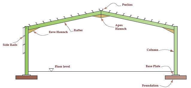
In most instances, the frame is assumed to be nominally pinned at the base, even where the frame may possess appreciable stiffnesses. This implies that the base plate to the portal frame is designed as a simple connection.
Haunches
As earlier stated, a haunch (Figure 3) is commonly provided in the eaves and apex of portal frames, and its provision is to enhance the flexural resistance of the rafters where the bending moment appear to be greatest, instead of sizing the rafters based on the value of the flexural moment at the eaves. The haunch also doubles as a stiffener to the frames, increasing stability and reducing deflections. The presence of a haunch also facilitates the use of bolted connections.
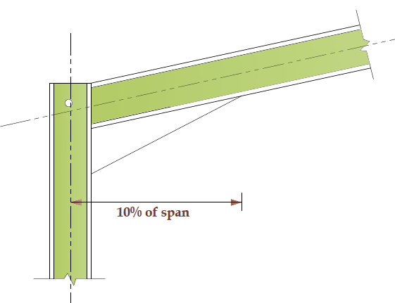
The Eaves haunches are normally cut from a hot rolled section slightly larger or at least the same as the rafter and welded to the underside of the rafter. In the design of the frame, it is desired for the flexural hogging moment at the eaves to be approximately equal to the sagging moment at the apex, to achieve this, the length of the eaves haunches is kept equal to 10% of the frame span. The apex haunch is also cut from a hot rolled section, the same size as the rafter or from steel plates, however in contrast to the eave haunches, they are not provided for enhancing flexural resistance but to facilitate the bolted connections between the rafters.
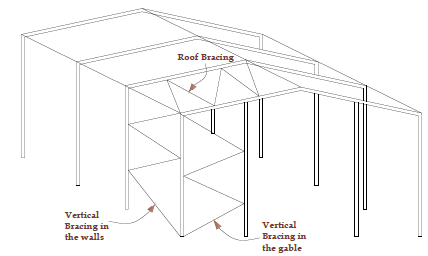
Bracings
As with most steel structures, a portal frame structure requires braced bays to transfer the applied lateral forces to the ground. The braced bays contains both horizontal bracings provided in the plane of the rafters and vertical bracings in the plane of the side walls (Figure 4). Most often the braced bays are provided at both ends of the building and in certain cases an additional braced bay might be needed along the length of the building, depending on the magnitude of the lateral loads being envisioned. When bracings are provided at the end frames, the roof bracings intersect with the top of the gable columns, hence it is able to transfer the loads in the plane of the roof to the eaves.
When it is impossible to accommodate longitudinal stability via the provision of braced bays, an alternative solution is to provide a rigid frame in the longitudinal direction. (Figure 5).
Common steel section used for bracings in a portal frame structure include but not limited to circular hollow section (CHS), angles and flats. The flats are a favourite for the vertical bracings.
Gable Frames
The end frames of portal frame structures are referred to as the gable frames. The gable frames consist of steel columns at intervals connected by rafters (See figure 6) just like the main frames, but in addition, they contain one or more braced bays in the plane of the frame. In a gable frame, the gable columns span like a vertical beam from the ground to the portal frame.

Alternatively, a main frame may be used as the gable frame, especially where future modification/expansion is envisaged. Here, the main frames are used to reduce the impact of any future structural works.
Secondary Steelwork
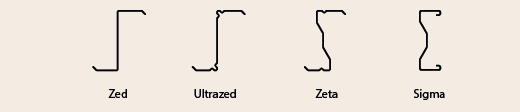
The secondary steelwork includes members such as purlins, side rails, eave beams etc. They are generally provided from cold-rolled steel sections. Figure 7 shows some common section types used for purlins and side rails in a portal frame structure.
The primary function of the purlins and side rails is to transfer the gravity and lateral forces applied on the cladding to the primary steel frame. The purlins and side rails may also be used as restraints to the rafters and columns at certain positions.
Forms of Portal Frame Structures
Aside from the symmetrical pitched roof that has being used to describe portal frame structures so far, a portal frame structure may also take any of the different structural forms described below depending on the brief. It is important to state here, that all other forms as would be described are only an extension/modification of the pitched roof frame. Hence the various forms as well as the information that is provided about them is not meant to set some limit on their use.
Crane Portal Frame
A crane portal frame is particularly suited and designed for portal frame structures of industrial workshops, where there’s a special requirement for a travelling crane. Column brackets are usually provided on the portal frame columns connecting a rail which ultimately support the weight of the moving crane and the forces on it (Figure 8).
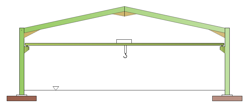
In a crane portal frame, the deflection at the eaves is usually more due to the forces on the crane, thus it is usually required to provide a tie or design the column bases as a rigid connection other than the nominally pinned connection typically assumed in the design of portal frames.
Tied Portal Frame
A tied portal frame (Figure 9) employs the use of a tie to resist horizontal movement of the frames at the eaves resulting in a reduction in the ensuing bending moment in the portal frame. A tied frame may be required for two reasons – there is a necessity to limit the horizontal movement of a frame or the movement of a crane along the frame’s spanning is to be accommodated.
When a tie is provided in a portal frame, a surge in the axial forces in the frame would be noticed, this often necessitate a full blown second order analysis, hence a software package with second order analysis functionality will be required in analyzing this structural form.
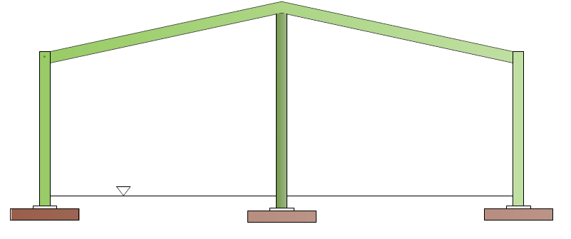
Propped Portal Frame
Where the span requirement of the portal frame structure is so large such that a clear span is unachievable or where there is no special requirement to have a clear span, a propped frame can be used. The propped portal (Figure 10) frame uses an additional third leg column to prop the frame at the apex, thereby reducing the forces that would have otherwise being obtained in the rafters, ultimately reducing the rafter size and the horizontal shear force at the base.
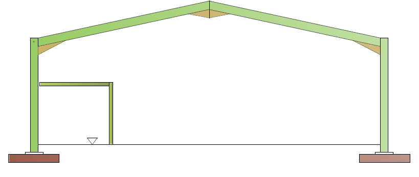
Portal Frame with Mezzanine Floor
Sometimes there is a requirement for an office, or generally an enclosed space or floor within a portal frame structure. The use of a mezzanine floor of partial width provides the opportunity to achieve this functionality (See Figure 11).
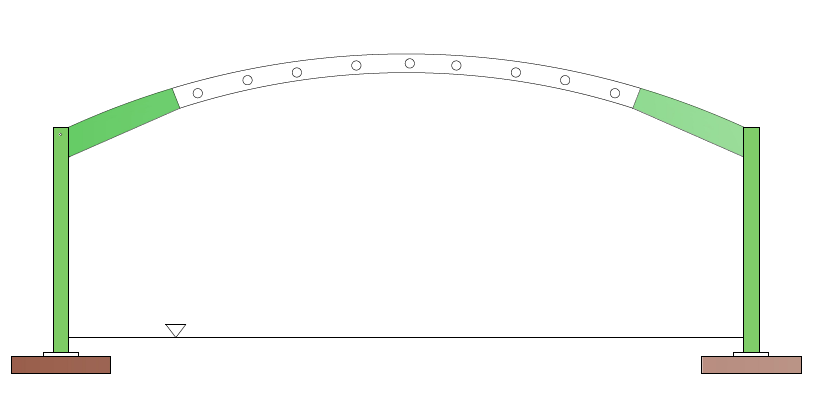
Curved Rafter Portal Frame
A curved rafter portal frame as the name implies uses a curved rafter in the fabrication of the frame (Figure 12). Curved portal frames are generally an architectural requirement.
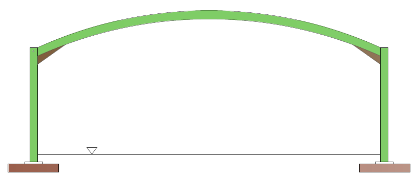
Rafters often exceeding 20m require splices due to the transportation/fabrication constraints. The rafters are modelled as straight members and guidance can be obtained from the Steel Construction Institute publication: Guidance on the stability of curved rafters in portal frames.
Cellular Beam Portal Frame
Cellular beams may be provided for use as the rafters in a portal frame structure strictly for architectural/ aesthetic reasons or when dealing with very long spans (Figure 13). Where transportation constraints would’ve necessitated the use of splices, they should be carefully detailed to preserve the architectural features.
As with cellular beam sections, they cannot develop plastic hinges, hence the advantage of plastic analysis commonly available to other forms of portal frames is not available to this, only elastic design can be carried out.
Preliminary Aspects of Analysis and Design
The conceptual design stage of any structure must take into cognizance a series of interconnected factors influencing on the overall design, a portal frame is not different. The frame dimension is critical to determining the overall height and width of the frame to give adequate building space for the internal functions of the building. The frame designer must decide on the following at the conceptual design stage.
Clear span and height
The clear span and height required by the client as evident in the architectural drawings is the key to determining the dimensions to be considered for use in the analysis and design. The architectural requirement for clear span is often the dimension between the internal flanges of the columns, the span used for design is the centre-centre dimension, hence this would be greater than the architectural clear span by the column section depth.
The clear height of the frame is measured from the finished floor level to the underside of the haunch or suspended ceiling. This will be determined using the specified internal floor height specified in the architectural drawing.
Main frames
A typical main frame in a portal frame structure should be characterized by the following1:
- Span of (15 -50m)
- Clear height of (5-12m)
- A roof pitch between (5°-10°)
- Frame spacing between 6 and 8m
- Haunches provided in the rafters at the eaves and apex
- A stiffness ratio between the column and rafter section of approx. 1.5
Position of restraints
Preliminary sizing of portal frame design is carried out using the resistance of the steel sections to their cross-section resistance to flexure, shear and axial forces. At the detail design stage, the resistance of the chosen sections to buckling would need to be carried out, with restraints positioned at the critical areas.
Buckling is usually less critical in the rafters due to the restraints from purlins, although sometimes additional restraints might be required. However, the same cannot be said for the columns, as there is usually more inhibition to positioning rails to provide restraints due to requirement for openings within the elevations of the buildings. Where intermediate restraints are impossible, the buckling resistance of the column will most likely determine the preliminary sizing of the columns. Thus, it is very essential at this early stage to understand if provision of continuous side rails is allowed on the frame elevations. Only continuous side rails can be guaranteed to effectively restrain the column. Side rails occasionally interrupted by the requirement for doors and windows cannot be relied on as providing effective restraints1.
Selection of material and sections
Having established the frame dimensions and use of restraint in resisting buckling, the frame designer must now select trial sections that would be used to check the analysis and design. The steel sections typically used in portal frame design are usually grade S355 steel.
For portal frames designed using plastic analysis, the classification of steel sections at locations where the formation of plastic hinges that rotate is likely must be Class 1, compact section can be used elsewhere.
See: Assessing the Stability of Frames
Sources & Further Reading
- The Steel Construction Institute (2012) Elastic Design of Single-Span Steel Portal Frame Buildings to Eurocode 3 (P397), Ascot, Berkshire: SCI
- The Institution of Structural Engineers (2010) Manual for the design of steelwork building structures to Eurocode 3, London: The Institution of Structural Engineers
- Institution of Structural Engineers (2014) Technical Guidance Note 12 (Level 2), The Structural Engineer, 92 (6), pp. 32-36
The analysis and design of portal frame structures will be presented in subsequent articles, please stay glued!
Thank you, and please share this post