Structural steel elements are amenable to failure due to lateral torsional buckling, when measures that recognizes this risk have not been considered in design. This article briefly, explains how the structural engineer can deal with lateral torsional buckling when analyzing steel structures.
Lateral torsional buckling is a very critical phenomenon that occurs in structural steel elements subjected to bending or sometimes combined bending and twisting. It occurs when a structural element, for instance, a steel beam bends about its major axis under load, thus causing the compression flange to buckle. This buckling can cause the steel beam to twist or rotate out of plane, resulting in an unstable structure.
When designing steel elements, it’s best to avoid structural arrangement that are vulnerable to lateral torsion buckling. Lateral torsional buckling can be prevented in a simply supported beams, by restraining its compression flange, thus preventing it from rotating along its axis. Longer, thinner and flexible steel elements are more prone to lateral torsional buckling, hence one-way engineers aim to avoid lateral torsional buckling is by restricting the length of steel elements and by use of stiffer than usual elements. Lateral torsional buckling can also be avoided by utilizing a closed steel section in place of an open steel section. Closed steel sections are invulnerable to lateral torsional buckling by virtue of their warping constant being zero.
However, sometimes, lateral torsional buckling cannot be completely avoided but controlled. The structural engineer only has the option of designing the structure to deal with it. Thus, the vulnerability of steel elements must be fully understood and allowed for by the structural engineer when designing structures that consist primarily of steel elements.
Methods of restraint
To control lateral torsional buckling in steel structures requires the engineer to strengthen the steel structure. This is usually achieved via the provisions of restraints.
Eurocode 3 (BS EN 1993-1-1), Clause 6.3.2, for example, explains that in order for a steel beam element to be classed as ‘restrained’, its compression flange must have sufficient restraint so as not to be susceptible to lateral torsional buckling. Beams with certain types of cross sections e.g., closed hollow sections with a height/depth ratio of less than or equal to 2, are not susceptible to lateral torsional buckling.
As a general rule, a restraint to a top flange of a beam must be capable of resisting a force that is equivalent to 2.5% of the ultimate compression load in the top flange of the beam element it is restraining.
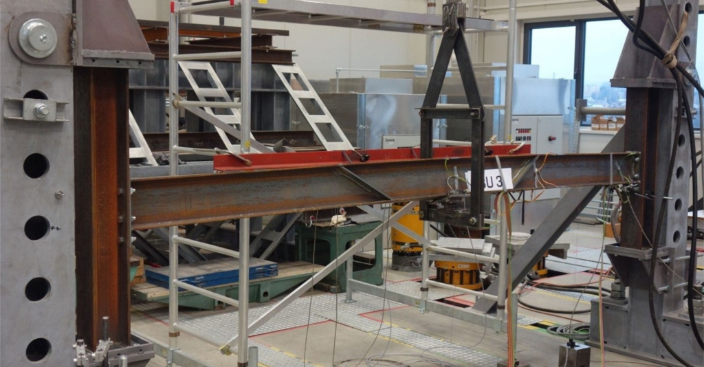
The methods of restraining steel beams are dependent upon meeting this load resistant requirement – and for most structures (such as concrete) – can be easily met. Care must be taken however when determining the capacity of the floor structure to act as a restraint, with regards to how it is supported by the steel beam. If the top flange of the beam is not directly supporting the floor structure, then it is not restrained. Examples of this are shown in Figures 1 and 2.
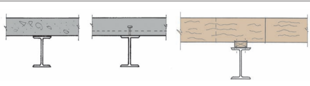
Note that the examples in Fig. 2 can be analyzed on the basis that they provide a stabilizing load, even if the top flange is unrestrained. More detailed advice on how to carry out such analysis and other methods of continuous restraint can be found in The Steel Construction Institute Publication Stability of Steel Beams and Columns.
Intermediate restraint
Sometimes, steel beams may be provided with restraints at discrete locations along their length known as intermediate restraints. The need for intermediate restraints typically occurs where openings within a floor structure require additional support, which tend not to have the floor structure sitting on them.
The integrity of the restraint must be that it is fixed to a point of support that can withstand the axial load applied to it. Examples of such supports include walls and braced elements. It is important to note that restraints cannot be simply fixed back to an adjacent beam, as the support is not stiff enough to withstand the applied load. The presence of intermediate restraints reduces the effective length of the steel beam, which results in a smaller section size of the element than if there were no restraints at all.
Restraints to cantilevers
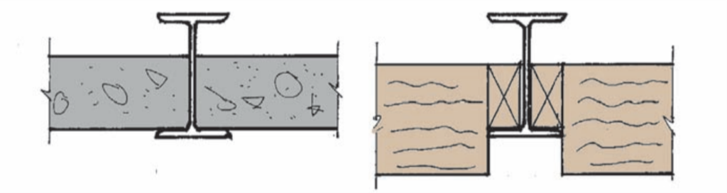
A special type of steel beam element whose design is impacted on the level of lateral torsional restraint present, is the cantilever beam. The buckling mechanism is somewhat different to simply supported beams in that the bottom flange needs to be restrained more than the top flange, as shown in Figure 3.
When assessing the amount of restraint provided, the engineer must consider how the beam is supported and the level of torsional restraint that is offered at its end. For most cantilever steel beams, the restraints can either be provided at the supports or at the tip of the cantilever. Either of these options have an impact on the design of the cantilever beam and must be considered in order to arrive at an accurate result.
Restraint to Trusses
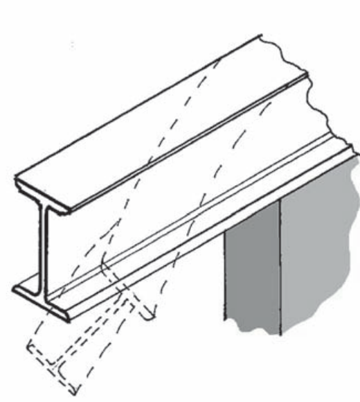
Like beams, trusses also require restraint, but they are more often than not placed within the roof structure of a building. This can lead to them being subjected to uplift loads due to negative air pressure from prevailing wind. This is known as ‘wind reversal’ and has an impact on the design of the bottom chord of the truss, which is normally subjected to tension loads. Reversal causes the bottom chord of the truss to withstand compression loads, which can result in a buckling failure. To overcome this, lateral restraints are installed (Figure 4).
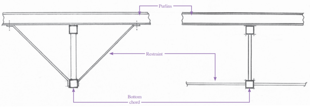
The restraints provided are designed for the restraint force as a strut and tie only.
Worked Example
A 8m long, 686x254x140 UB is supporting a UDL of 12 kN/m ultimate load and lateral restraints at 3rd points along its length. Calculate the axial force that needs to be resisted by the restraints.
Properties
Zxx = 3987cm3; b = 253mm tf = 19mm
Ultimate Bending Moment
M =\frac { w l^{2} }{ 8 } = \frac { 12\times8^2 }{ 8 } = 96kN.mCompression Stress in Flange
\sigma=\frac {M}{Z}=\frac{96\times 10^6}{3987 \times 10^3} =24.1N/mm^2Compression Force in Flange
F =\sigma bt_f=24.1\times 253 \times 19 =115.8kN
2.5\%F = 0.025 \times 115.8 =2.9kN
Force to Resist
=\frac {2.9}{2}=1.45kNAlso See: Designing a Laterally Unrestrained Steel Beam
Sources & Citations
Institution of Structural Engineers (2012) Lateral Torsional Buckling. The Structural Engineer, technical guidance (level 2).
Institution of Structural Engineers (2010). Manual for the Design of Steel-work Buildings to Eurocode 3.