This article is an overview of the IstructE document (How to Calculate Embodied Carbon). It focuses on the lifecycle module A1-A5 (embodied carbon from the production stage up to the end of the construction process).
It is not up for debate that the earth’s climate is changing quite rapidly. The global consensus is that drastic measures must be inaugurated if we’re to bring down rise in global temperatures as a result of the emissions of greenhouse gases. Scientist has advised that 1.5°C is the tipping point beyond which the effect of climate change becomes so adverse such that it’s irreversible.
Should we fail in this quest, there would be significant consequences, some of which have begun to manifest in the form of drought, flooding, strong storms, tornadoes and the like. In fact, it is estimated that more than 10 major cities of the world are bound to become unlivable by 2050. Thus, there is a pressing need to cut down carbon emissions.
In an earlier article titled: the responsibility of the engineer in the climate emergency. This writer highlighted the significant contribution of structural engineering to climate change and the great role structural engineers have to play in reducing the embodied carbon of structures. Four strategies were presented, all of which ultimately aims to reduce the volume of materials used up in construction. Therefore, there is a need to estimate the embodied carbon in our structures, if we aim to reduce material quantities. This will afford engineers the ability to target carbon reductions through material selection, specification, efficiency and reuse.
This article is an overview of the IstructE document (How to Calculate Embodied Carbon). It focuses on the lifecycle module A1-A5 (embodied carbon from the production stage up to the end of the construction process). The reader is advised to use the full guide when carrying out calculations as this gives a fuller and better understanding of the background processes and lifecycle stages.
Calculating Embodied Carbon
The early phases of design are when embodied carbon calculations are most crucial. In order to implement adjustments in light of your embodied carbon estimation, you must have the necessary time and space. For each lifecycle module being taken into account, the basic premise of an embedded carbon calculation is generally to multiply the quantity of each material or product by a carbon factor, which is commonly quantified in kgCO2e per kg of material:
Embodied Carbon = material quantity × carbon factor
Throughout the design phase, it is ideal that the accuracy of the estimate for the quantity of each material or item will increase. The carbon factors, which are broken down per lifecycle module, are educated guesses whose precision increases as more is understood about the project’s procurement procedure.
It should be noted that other components of an embodied carbon calculation have a different process, for instance, estimating site activity emissions (A5a), which will be described later in this article.
Using the equation above, the embodied carbon for a whole structure may be readily assessed even at the concept stage, allowing design solutions to be evaluated quantitatively with the other elements of sustainable design.
Material Quantities
There are several ways by which the engineer can arrive at material quantities depending on the stage of design. If the design is at the detailed design stage the actual material quantities can be estimated and used for the computation. However, if it’s at the concept stage, it’s appropriate to estimate member sizes using rules of thumb and preliminary sizing assumptions from experience. Quick calculations or even a scheme design can also be used.
Whatever the case may be engineers are advised not to skip embodied carbon calculation at the early design stages as a result of accurate material quantity estimate, but to instead make assumptions and realize the limitation of these assumptions.
Life Cycle Stages & Modules
Depending on the stages of a material or product life, the amount of embodied carbon or carbon released will vary (Figure 1). Hence, there is need for the engineer to be familiar with lifecycle stages. Individual modules make up a lifecycle stage. For instance, module A1-A3 make up the product stage while A1-A5 cradles to the completion of construction. This is the minimum scope for embodied carbon calculation that takes into cognizance the start to finish of a construction project and as well the scope of the article.
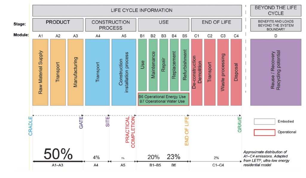
Since the production stage (A1-A3) and construction process stage (A4-A5) phases are likely to account for the vast majority of the embodied carbon associated with our designs—and because these emissions must be addressed most urgently, oftentimes during the conceptual stage—this article only provides information on module (A1-A5). Please refer to CEC, which provides inputs for all lifespan modules as well as crucial background data for Modules A1-A5 that should be reviewed before doing carbon calculations, for information on further stages (B, C, and D) and other materials.
Carbon Factors
As earlier stated, the carbon factor is a function of the amount of carbon emitted either during the production or use of a material. Again, this factor depends on the lifecycle stages.
Typical carbon factors for certain structural materials at stages A1–A3 are provided in the CEC. The range of each component might be wide, so as you get more definite about the source and specification of your product, you should look for more precise factors via the supply chain. Environmental product declarations (EPDs), which include carbon factors for their products, are frequently provided by manufacturers.
Production Carbon Factors (A1-A3)
It isn’t up for debate that much of the embodied carbon associated with the construction of structures occurs at the production stage. Think about this along the lines of the 4000million tons of cement or the 900million tons of steel that is produced yearly through a process that emits carbon. Thus, there is no surprises that the largest contributor of a structure’s embodied is associated with the A1–A3 module.
The material specification – varies with constituent materials, how and where it is created – determines the A1–A3 embodied carbon factor (ECF). For instance, the A1-A3 factor for concrete changes depending on cement content and the proportion of Portland cement (PC) replacement, while the factor for steel sections varies depending on the amount of recycled material and the manufacturing process.
Rebar is a prime illustration of how wide the range may be. The A1-A3 ECF for UK-made rebar is 0.684kgCO2 e/kg, whereas a bar produced in the UAE with no recycled component may be closer to 2.1kgCO2 e/kg.
CEC Table 2.3 has a more comprehensive list of material ECFs, including generic concrete, screeds, steel hollow sections, steel plate, galvanized steel decking, dense concrete blocks, brick wall build-ups (/m2), stone, aluminum, and glass.
Transport Carbon Factors (A4)
Transport carbon factor, A4 emissions generally account for 10% or less of the total carbon contained in a construction and are mostly related to the transit of goods from the manufacturer to site. A4 ECF is affected by the manner of transportation and distance covered.
Typical values of transport emission values for different modes of transport can be obtained in Table 2.4 & 2.5 of CEC. However, one must emphasize the need to always utilize a more reliable and accurate estimate, and this can be obtained from the material source.
Construction Installation Carbon Factors (A5)
Over the course of a project, A5 emissions are anticipated to represent a negligible but not insignificant portion of the structural embodied carbon. The emissions are divided into two categories and vary according to construction methodology, material preferences, site configuration and location. A5w emissions are those related to materials wasted on site, whereas A5a emissions are those brought on by site activities (construction equipment, site operations, etc.)
Material Wastage A5w
The A5w carbon factor represent the amount of carbon that is emitted during manufacturing, transportation, and waste disposal. It uses another factor known as WF to actually estimate the proportion of the amount of material brought to site that is wasted.
To determine the A5w factor, the WF is multiplied by the total of the pertinent ECFs.
A5w = WF × (A13 + A4 + C2 + C34)
Where:
- WF is the waste factor and its value is based on the anticipated percent waste rate (See Table 2.6 of CEC),
- A1-3 is comprised of emissions from A1 to A3 for producing waste materials, including sequestration factors for wood
- A4 for moving the waste materials to the destination
- Transporting the garbage away from the facility will utilize C2 (assuming 50 km by road to the closest reuse/recycling point = 0.005 kgCO2 e/kg in the absence of better data).
- In the absence of better data, assume 1.77kgCO2 e/kg for timber products* and 0.013kgCO2 e/kg for all other materials (see RICS, 20176, Section 3.5.3.4). C34 is C3-C4 emissions for processing and disposal of the waste material.
Site Activities A5a
By far the most difficult to estimate is the site activities carbon factor because data must be documented throughout the cause of the project execution. However, to contribute to an accurate as-built embodied carbon calculation, site activity emissions must be tracked throughout construction and added to the estimation. Site activity emissions may be calculated from on-site energy usage and fuel use. Any information gathered on site activity emissions can also be utilized to estimate A5a emissions from upcoming projects.
Prior to the commencement of construction, A5a emissions for the entire structure can be calculated using data from past projects or industry research.
When calculating the embodied carbon for an entire building in the UK, the RICS handbook gives a rate of A5a = 1400kgCO2e per £100 000 construction cost to be used in the absence of site-specific data (see Section 3.5.2.2). However, based on projections of the percentage of site activity emissions attributable to its construction (based on construction effort, necessary machinery, and time), a factor of this figure can be assumed for superstructure and substructure only.
This may be anywhere in the range of 50% for the building of the superstructure and substructure alone. This suggests that in the absence of better data, a rate of A5a = 700kgCO2 e per £100 000 might be used for estimations.
Future versions of CEC are anticipated to have more details on this subject as site activity emissions are better recorded and comprehended.
Worked Example
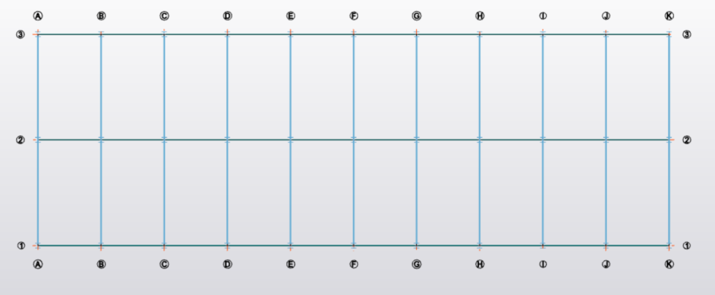
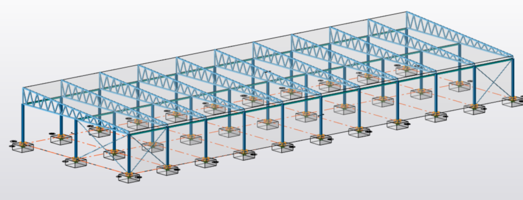
A Single-Storey steel frame at concept design has a gross internal area (GIA) of 1210m2 and a total construction value of £1,200,000. Estimate the embodied carbon in this design? See Figures 2 & 3
Quantities
Concrete in Foundation & Ground Floor Slab
- Assume 150mm thick ground bearing slab = 0.15×1210 = 181.5m3
- Pad Footings (Assume) 1.5m × 1.5m × 0.3m × 30 = 20.25m3
Total mass of conc. = (181.5+20.25) × 2.4ton/m3 = 484.2tons
Rebar in Foundation
Assume 90kg/m3 of reinforcing bars:
Total mass of rebars = (181.5+20.25) × 0.09=18.2tons
Steel Frame
Assume 25kg/m2 of structural steel (allowance include connections)
Total mass of structural steel = 1210 × 0.025=30.3tons
Carbon Factors
Concrete
- A1–A3 (production) = 0.14kgCO2 e/kg (Assumed)
- A4 (transport) = 0.005kgCO2 e/kg (from Table 4, assume locally manufactured)
- A5w (waste) = WF × (A1–A3 + A4 + C2 + C3–C4) = 0.053 × (0.14 + 0.005 + 0.005 + 0.013) = 0.008kgCO2 e/kg (WF from Table 5, concrete in situ, and default C2 and C3–C4 values)
Rebar
- A1–A3 (production) = 0.684kgCO2 e/kg (from Table 2, typical UK Specifi c Rebar EPD)
- A4 (transport) = 0.032kgCO2 e/kg (from Table 4, assume manufactured in UK)
- A5w (waste) = 0.053 × (0.684 + 0.032 + 0.005 + 0.013) = 0.039kgCO2e/kg (WF from Table 5, steel reinforcement, and default C2 and C3–C4 values)
Steel Frame
- A1–A3 (production) = 2.25kgCO2 e/kg (Assumed)
- A4 (transport) = 0.032kgCO2e/kg (from Table 4, assume manufactured in UK)
- A5w (waste) = 0.010 × (2.25 + 0.032 + 0.005+0.013) = 0.023kgCO2 e/kg (WF from Table 5, steel frame, and default C2 and C3–C4 values)
Embodied Carbon
Embodied Carbon = material quantity × carbon factor
Concrete
- A1-A3 (production) = 0.14 × 484.2 = 67.8tCO2e
- A4 – Transport = 0.005 × 484.2 = 2.4tCO2e
- A5w – Waste = 484.2 × 0.008 = 3.9tCO2e
Embodied carbon in concrete = 67.8+2.4+3.9 = 74.1tCO2e
Rebar
- A1-A3 (production) = 18.2 × 0.684 = 12.5tCO2e
- A4 – Transport = 18.2 × 0.032 = 0.6tCO2e
- A5w – Waste = 18.2 × 0.039 = 0.7tCO2e
Embodied carbon in rebars = 12.5+0.6+0.7= 13.8tCO2e
Steel Frame
- A1-A3 (production) = 30.3 × 2.25 = 68.2tCO2e
- A4 – Transport = 30.3 × 0.032 = 1.0tCO2e
- A5w – Waste = 30.3 × 0.023 = 0.7tCO2e
Embodied carbon in steel frame = 68.2+1.0+0.7= 69.9tCO2e
Others
A5a (site activities) = 0.7 × (£1200 000 / £100 000) = 8.4tCO2e
Overall Carbon Footprint (A1-A5) = 74.1+13.8+69.9+8.4= 166.2tCO2e
See: Multi-Level Basement Construction – The Londoner Hotel
Sources & Citation
- The Institution of Structural Engineers. Climate emergency. Available at: www.istructe.org/resources/climate-emergency/ [Accessed: July 2023]
- The Institution of Structural Engineers. How to Calculate Embodied Carbon. Available at: www.istructe.org/resources/ [Accessed: 2023]
- The Institution of Structural Engineers. A Brief Guide to Calculating Embodied Carbon. Available at: www.istructe.or / [Accessed: July 2023]