This article attempts to give a background on the subject of frame stability with a primary focus on the practicalities of structural steel-work design to Eurocode 3
For every structure and structural material, frame stability is an important area of consideration. Designers of structural steel-work were the first to recognize the importance of assessing the stability of frames. Even though the requirement to ensure that frames are made sufficiently stiff has always being included in earlier codes, no guidance on assessing frame stability was explicitly given. The topic only became a subject of importance in BS 5950 now superseded by BS EN 1993.
This article attempts to give a background on the subject of frame stability with a primary focus on the practicalities of structural steel-work. The article does this using the guidance specified in Eurocode 3, however, there is no doubt that designers working to different codes of practices and with different materials will gain useful insights on the subject.
Frame stability can be defined as the effect of displaced vertical loads that are no longer concentric with their normal positions. This effect usually manifest in the form of lateral displacement which can either be caused by externally applied load such as wind, or due to the out of plumb of the frame by some degree. The latter is mostly the case and leads to the vertical loads applied on the frame being displaced. The displaced vertical load in turn causes further lateral displacement. This behaviour is classified as Second-Order Effect and most design codes require that the magnitude of this effect be assessed and allowed for within the design where necessary.
Although second-order effect described above can be ignored in some frames where their effects are small enough, they’re always present and must be always be checked.
Defining the Terminologies
Structural steel-work designers oftentimes refer to sway sensitive frames and non sway frames. The latter description is false since all frames under the application of loads will sway. The distinction between the two terminologies in real sense lies in the significance of the sway effects. Some designers also refer to second-order effects as P-delta effects. To be clear P-delta effects are due to the likely initial imperfections within the length of members. These are usually allowed for automatically in the actual design of structural members, hence would not be addressed in this article.
Other designers also refer to “sway frames” when a proper terminology would probably be “unbraced frame.” In an unbraced frame, resistance to lateral loads is provided by the continuity of structural elements (Moment resisting frames). Whereas, braced frames in contrast to unbraced frames derive their resistance to lateral forces from the disposition of steel bracings and diagonal steel members or perhaps by the provision of a concrete core. This distinction as well as correct understanding of these terminologies is very important and should be given utmost importance, because a braced frame can be “sway sensitive.” Same way an unbraced frame can be sufficiently stiff such that second order effects are then small enough to be ignored.
The Elastic Critical Load
Before the stability of a steel frame can be assessed, one very important parameter must be determined. This is known as the elastic critical load, Pcr. The elastic critical load can be described as the load at which the entire frame will collapse under the application of vertical loads only. It is a function of the frames property and shape of loading. For example, consider a frame subjected to vertical loads only (Figure 2). If the vertical loads on this frame is gradually increased, at some point the frame will collapse. Now consider that this frame was initially out of plumb by some degree whilst the vertical loads was increased, the additional deformations due to the vertical loads just before reaching the elastic critical load would be significant. Hence the ratio between the elastic critical load and the applied load is an important pointer towards second order effects.

In EC3 this ratio is known as Fcr/FEd. This ratio indicates that, as FEd increases the ratio reduces, indicating increased sensitivity to second order effects.
The Eurocode Approach to Frame Stability
The basic procedure involves estimating the applied vertical loads on the frame and the magnitude of elastic critical load for the frame and shape of loading. Estimating Fcr would often be a tedious task for manual analysis. Thus software have been frequently used to determine it magnitude. However, as an alternative, design standards provides a simplified but conservative method of determining alpha critical. In Eurocode 3 assessment of frame stability is explicitly dealt with in section 5.2.
The underlying expression can be written as:
{ \alpha }_{ cr }=\left[ \frac { { H }_{ Ed } }{ { V }_{ Ed } } \right] \left( \frac { h }{ { \delta }_{ h,Ed } } \right)Where:
h is the storey height
HEd is the horizontal shear at the base of the storey. This is equal to the sum of the lateral loads applied at all floor and roof levels above the storey under consideration. In general, these lateral loads will be the Equivalent Horizontal Forces (EHF) prescribed in Clause 5.3.2 together with any wind forces ( if the wind is part of the combination of actions being considered).
VEd is the total vertical load at the base of the storey. This is equal to the sum of the vertical loads from all the floors and roof, above the storey under consideration.
δH.Ed is the lateral displacement over the storey i.e. the displacement between levels due to the lateral loads only.
This expression is evaluated for each storey, starting from the lowest storey to the top of the frame. In simple steel frames containing several similar bracings, the magnitude of δH.Ed can be determined by analyzing just one bracing. Where this is the case, the horizontal and vertical actions applied should be in proportion of stiffnesses.
It is as well important to state that, the approximate formula given in section 5.2 of EC3 has certain limitations. It can not be applied to irregular frames or portal frames with significant axial forces in the rafters.
Second-Order Effects
The primary reason for assessing the stability of a frame is to determine its sensitivity to sway, in order words its propensity to second order effects. Eurocode defines when second order effects are small enough to be ignored. For frames designed elastically, second order effects may be neglected if αcr is greater than 10. If αcr is less than 10, the frame is susceptible to buckling failure and a second order analysis needs to be carried out. However, the Eurocode again simplifies this through the use of an amplifier, for amplifying the horizontal actions (wind, EHF’s etc.).
\quad load\quad amplifier\quad =\quad \frac { 1 }{ 1-\frac { 1 }{ { \alpha }_{ cr } } }Note: that the amplification factor can only be applied if αcr is greater than 3. Where the reverse is the case, a full blown second order analysis must now be undertaken. The simple amplification is only one way to allow for second-order effects. There are other approaches, including the use of software.
To conclude, steel frames are relatively lightweight when compared to concrete frames, so sensitivity to second order effects should always be expected. There is nothing absolutely wrong with a structure having αcr less than 10. It is indeed expected that many frames will fall into this category, hence the provisions in the codes. The use of software which will allow for these effects is one convenient approach. For straightforward frames, the Eurocode contains a simple method to assess the significance of second order effects and how to allow for them if necessary.
Worked Example
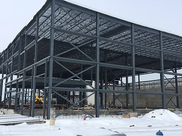
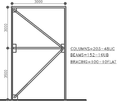
Figure 2.0 shows the typical braced bay of a one suspended floor office building consisting of UKB’s, UKC’s and diagonal bracings. Assess the sway sensitivity of the structure. Are second order effects significant? if so what are the amplification factors.
The design actions has been apportioned according to the stiffnesses of the braced bays and are shown as Table 1 & 2. Table 1 shows the design data where imposed load is the leading variable action and wind as accompanying variable action, while combination two shown as table 2 has wind as leading variable action with the imposed load as accompanying variable action. In each case, EHF has been considered and included in the horizontal actions.
See: Application of Notional Loads on Structures
| Floor | Vertical Actions (kN) | Horizontal Actions (kN) | Total Deflection (mm) |
| Roof-1st | 4034 | 34.1 | 9.3 |
| 1st-Ground | 9176 | 73.6 | 5.1 |
| Floor | Vertcal Actions (kN) | Horizontal Actions (kN) | Total Deflection (mm) |
| Roof-1st | 3519 | 45.3 | 11.9 |
| 1st - Ground | 7331 | 96.7 | 6.5 |
The last column in both tables shows the total displacement at each storey, this has been obtained by analyzing the frame for the horizontal loads only per requirement.
Load Combination One
{ \alpha }_{ cr }=\left[ \frac { { H }_{ Ed } }{ { V }_{ Ed } } \right] \left( \frac { h }{ { \delta }_{ h,Ed } } \right) a) Roof – 1st Floor
{ H }_{ Ed }=34.1kN\quad { V }_{ Ed }=4034kN;\\h =3000mm\\ { \delta }_{ H,Ed }=9.3-5.1=4.2mm { \alpha }_{ cr }=\frac { 34.1 }{ 4034 } \times \frac { 3000 }{ 4.2 } =6.04<10b) 1st – Ground Floor
{ H }_{ Ed }=34.1+73.6=107.7kN\\ { V }_{ Ed }=4034+9176=13210kNh\quad =3000mm\quad { \delta }_{ H,Ed }=5.1mm{ \alpha }_{ cr }=\frac { 107.7 }{ 13210 } \times \frac { 3500 }{ 5.1 } =5.6<10Therefore the worst case of αcr is = 5.6
\quad load\quad amplifier\quad =\quad \frac { 1 }{ 1-\frac { 1 }{ { \alpha }_{ cr } } } =\frac { 1 }{ 1-\frac { 1 }{ 5.6 } } =1.22Thus, all horizontal actions acting on the frame for combination one must be increased by 22% in order to allow for second-order effects.
Load Combination Two
a) Roof – 1st Floor
{ H }_{ Ed }=45.3kN\quad { V }_{ Ed }=3519kN;\\ h\quad =3000mm\\ { \delta }_{ H,Ed }=11.9-6.5=5.4mm { \alpha }_{ cr }=\frac { 45.3 }{ 3519 } \times \frac { 3000 }{ 5.4 } =7.15<10b) 1st – Ground Floor
{ H }_{ Ed }=45.3+96.7=142.0kN\\{ V }_{ Ed }=3519+7331=10850kNh\quad =3500mm\quad { \delta }_{ H,Ed }=6.5mm{ \alpha }_{ cr }=\frac { 142.0 }{ 10850 } \times \frac { 3500 }{ 6.5 } =7.05<10Therefore the worst case of αcr is = 7.05
\quad load\quad amplifier\quad =\quad \frac { 1 }{ 1-\frac { 1 }{ { \alpha }_{ cr } } } =\frac { 1 }{ 1-\frac { 1 }{ 7.05 } } =1.17Thus, all horizontal actions acting on the frame for combination two must be increased by 17% in order to allow for second-order effects.
We can conclude that this frame is sensitive to second-order effects and thus allowances must be made in it analysis and design.
Thank You!!!
What a great and enlightening article. Thanks very much sir 💕😊
cialis pills over the counter – generic cialis 10mg buy cialis online us
viagra 200mg over the counter – buy viagra in singapore viagra price per pill
cialis online 40 mg – original cialis generic cialis 2018 usa
ivermectin tablets – ivermectin lotion 0.5 where can i buy oral ivermectin
best slots to play online – casinoslotgam.com slots online
best male enhancement pills – impotence pills best natural ed pills
steroid prednisone – cost of prednisone prednisone 5
stromectol 3 mg tablet price – stromectol tablets ivermectin 3mg for lice
home remedies for erectile dysfunction – best online canadian pharmacy cheap erectile dysfunction pill
Дом Гуччи смотреть онлайн 2021
buy ventolin – ventolin 90 cheap albuterol
cytotec 200mg price in india – where can you buy cytotec in south africa cytotec 200mg tablets
where can i buy doxycycline capsules – best pharmacy online no prescription doxycycline doxycycline rx
where can i buy neurontin from canada – neurontin 600mg average cost of levothyroxine
can i buy viagra in india – generic prescription viagra
https://buypropeciaon.com/ – Propecia
cialis australia pharmacy – cialis europe online online pharmacy in canada cialis
смотреть фильмы онлайн бесплатно
vardenafil pills online – vardenafil online consultation cheap vardenafil
buy cialis online
ivermectin cream 1 – ivermectin for humans stromectol 2mg
how much is prednisone 10mg – prednisone pack order prednisone 40mg online
6000 mg accutane – accutane 10mg for sale where can you get accutane online no rx
онлайн
amoxicillin no prescription – buy amoxicilin noscript amoxicillin 500 mg
cialis daily for bph
cheap generic online viagra
methylprednisolone tablets uk – medrol 8mg 900 mg lyrica
Stromectol
sildenafil in india online – Generic viagra canada viagra generic coupon
http://buytadalafshop.com/ – buy cialis online
http://buystromectolon.com/ – Stromectol
generic tadalafil 20 mg price – Cialis free delivery cialis india cheap
generic finasteride international
Клятва лiкаря
Злое
Соври мне правду
Воспоминание
Кэндимен
Buy Cheap Tamoxifen
13576
1822
7916
buy ivermectin tablets – stromectol cost uk ivermectin dosage
50mg prednisone tablets – can you buy prednisone over the counter in canada prednisone 10mg prices
2418
furosemide coupon – clomiphene for sale buy lasix online no prescription