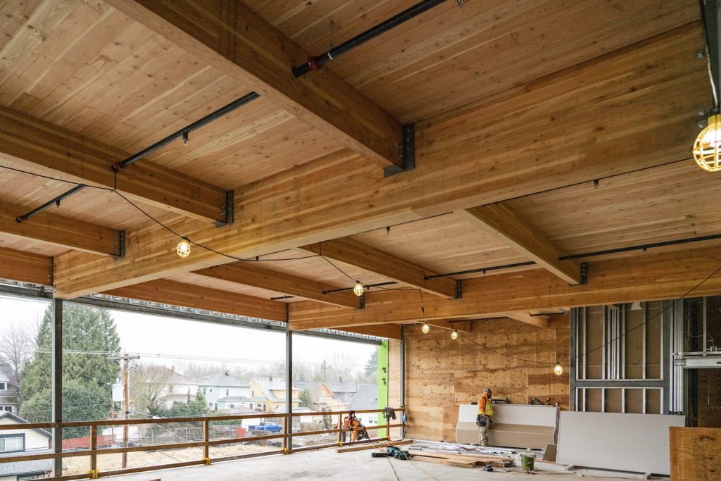
This article concerns the design of cross laminated timber floor, a floor made by stacking multiple layers of wood boards in alternating directions, which are then bonded together using a strong adhesive.
When it comes to flooring options, few materials can match the timeless beauty and warmth of timber. Timber floor panels have long been a popular choice for homeowners and designers alike, thanks to their durability, versatility, aesthetic appeal and eco-friendly properties. Whether you’re considering renovating your home or designing a new space, timber floor panels offer a range of benefits that make them a top contender.
Across a broad range of options, the cross laminated timber panels are one of the most suitable options for timber floors. In recent years, cross laminated timber (CLT) floor panels have emerged as an innovative and sustainable solution for the construction and design industry. CLT has been used to construct multi-Storey buildings, up to nine stories. This engineered wood product offers a range of benefits, from exceptional strength and stability to environmental advantages and design versatility. CLT is typically suitable for offsite construction, where the CLT panels are manufactured offsite and erected onsite via crane
Cross laminated timber floor panels are made by stacking multiple layers of wood boards in alternating directions, which are then bonded together using a strong adhesive. This crosswise lamination process gives the panels exceptional stability and load-bearing capacity. CLT floor panels are typically composed of three, five, or seven layers of solid wood boards, depending on the required strength and thickness.
See: Structural Design of Timber Joist to EC5
Member Verification
A CLT floor panel is typically a restrained flexural member hence, the design typically follows the same process of designing timber joists. (See quoted post above). The design is required to satisfy flexure and shear at the ultimate limit state, and a verification of deflection and vibration at the serviceability limit state.
Design for Flexure
To verify a CLT panel against flexure, the applied bending stress must be less or equal to the bending resistance stress. This can be expressed mathematically as:
{ \sigma }_{ m,y,d }\le { f }_{ m,y,d }Where:
- σm,y,d is the applied bending stress
- fm,y,d is the design bending resistance
{ \sigma }_{ m,y,d }\quad =\frac { { M }_{ y,d } }{ { W }_{ y } } \ { f }_{ m,y,d }=\frac { { k }_{ h }{ k }_{ sys }{ k }_{ mod }{ k }_{ crit } }{ { \gamma }_{ M } } { f }_{ m,k }Where:
- My,d is the design bending moment
- Wy is the elastic modulus of the section
- fm,k is the characteristic bending strength (N/mm2)
- γM is the material partial factor of safety taken as 1.3 in the case of solid timber
Design for Shear
Design against shear is ensured by comparing the maximum shear stress against the shear strength of the CLT section. To design against shear the following equation must be satisfied.
{ \tau }_{ d }\le { f }_{ v,d }Where:
- τd is the maximum shear stress
- fv,d is the cross-section shear strength
{ \tau }_{ d }=\frac { 1.5{ V }_{ Ed } }{ A_{eff} } \quad ;\quad { f }_{ v,d }=\frac { { k }_{ sys }{ k }_{ mod } }{ { \gamma }_{ M } } { f }_{ v,k }Where:
- Vd is the design shear force
- Aeff is the effective area of the section
- fm,v is the characteristic shear strength (N/mm2)
- γM is as defined earlier.
Deflection Verification
The final step is to verify the CLT section against deflection. Table 4 gives limiting values based on the variable-imposed loads and permanent actions applied.
| Use | Deflection Limit |
| Brittle Finishes e.g., floors | Span/250 |
| No Brittle Finishes e.g., roofs | Span/150 |
| Accidental e.g., fire | Span/20 |
Creep is a significant factor in the deflection of timber structural elements. To allow for this, the instantaneous deflection due to permanent actions is usually increased slightly (1+kdef) while the instantaneous deflection due to imposed variable actions is increased by (1+ψ2,1kdef) assuming only one variable action is acting. The sum of these deflection provides the overall deflection of the joist due to bending.
Worked Example
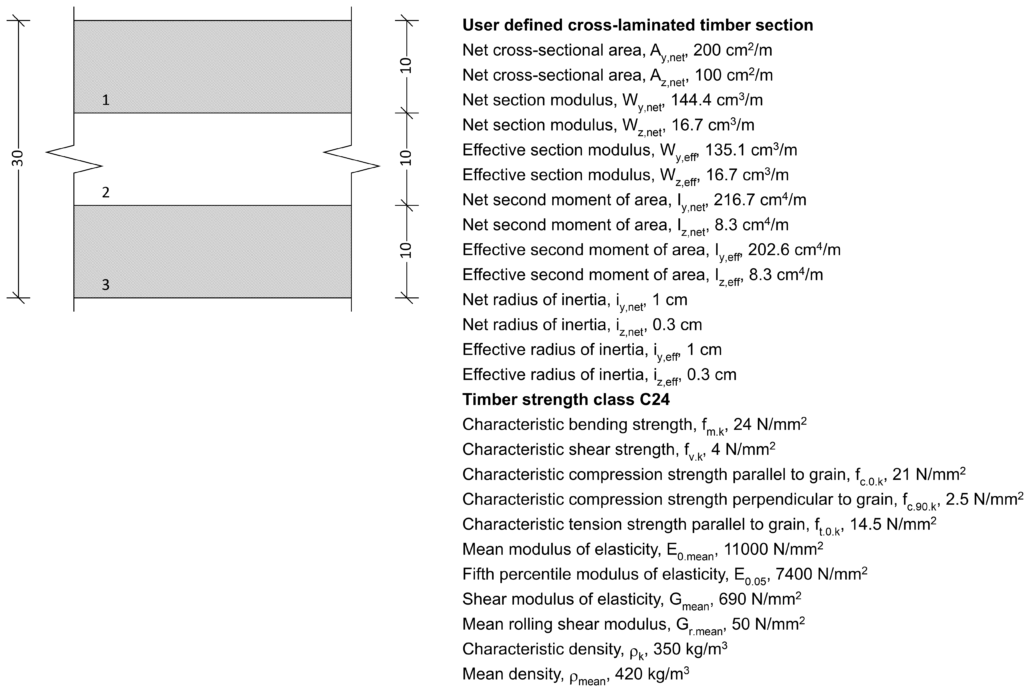
A timber floor in a new office development is required to span 6m, supporting a characteristics-imposed action of 1.5kN/m2. Supposing the joist are to be spaced at 1200mm and the self-weight of the timber boards fixed, and services is 0.75kN/m2, verify the adequacy of three layers of 10mm CLT boards in C24 timber to support this load. The load duration is medium, and the service class is 1

Actions
n_s=(1.35g_k+1.5q_k)
n_s=(1.35\times0.75)+(1.5\times 1.5)\\=3.26kN/m^2
Analysis
Bending Moment
M_{Ed}=\frac{n_sl^2}{8} =\frac{3.26\times1.2^2}{8}=0.59kN.mShear Force
V_{Ed}=\frac{n_sl}{2}=\frac{3.26\times1.2}{2}=1.96kNFlexural Design
Applied Bending Stress
{ \sigma }_{ m,y,d }\le { f }_{ m,y,d }\sigma_{m,y,d} =\frac{M_{Ed}}{W_y}=\frac{0.6\times10^6}{135.1\times 10^3}=4.37MpaDesign Bending Resistance
{ f }_{ m,y,d }=\frac { { k }_{ h }{ k }_{ sys }{ k }_{ mod }{ k }_{ crit } }{ { \gamma }_{ M } } { f }_{ m,k }=\frac{1\times1\times 0.8\times1\times 24}{1.25} = 15.36Mpa4.37Mpa <15.36Mpa \quad o.k
Shear Design
Applied Shear Stress
{ \tau }_{ d }\le { f }_{ v,d }{ \tau }_{ d }=\frac { 1.5{ V }_{ Ed } }{ bh } =\frac{1.5\times1.96\times10^3}{200\times 10^2}\\=0.15MpaShear Resistance
{ f }_{ v,d }=\frac { { k }_{ sys }{ k }_{ mod } }{ { \gamma }_{ M } } { f }_{ v,k }=\frac{1.0\times0.8\times4}{1.25}\\=2.56Mpa0.15Mpa<2.56Mpa \quad o.k
Deflection Verification
\delta_{max}\le\delta_{limit}Actual Deflection
\delta_{max}=\frac{5(w_g+w_q)l^4(1+k_{def})}{384EI_y}= 4.36mmLimiting Deflection
\delta_{limit}=\frac{span}{250}=\frac{1200}{250}= 4.8mm4.36mm <4.8mm \quad o.k
Adopt 3-10mm CLT Section in C24 Timber
Citation
- The Institution of Structural Engineers/TRADA (2010) – Manual for the design of timber buildings structures to Eurocode 5 London: The Institution of Structural Engineers/TRADA
- Porteous, J and Kerman, A. (2007) Structural Timber Design to Eurocode 5 Chi Chester: John Wiley & Sons
- The Institution of Structural Engineer (2012) – Technical Guidance Note Level 2 (18).
Thank You!