In earlier articles, we introduced aspects of concrete bridges, types of concrete bridges, design of concrete bridges. We also gave a description of the general parameters influencing the selection of concrete bridges. Of all the parameters listed, it was clear that construction is unarguably one of the most important factors influencing the choice of a bridge type. In fact, no major bridge can be designed without a thorough appraisal of how it will be constructed.
Over the next two articles in this series, we’ll focus on types of concrete bridges based on their peculiarities with construction methods.
Whilst construction methodology tends not to be an issue in many buildings, the same cannot be said for bridges. Nearly all bridges cannot and should not be designed without good knowledge of its temporary stages and construction methodology4. In most cases it is the construction method that determines the design. In selecting the best scheme, a bridge designer would aim to select a construction method and a bridge layout as they are basically entwined.
Each method will produce a very different spans, layout, sections, depth, thicknesses and details. For example, the design and detailing of a bridge built via launching is profoundly different from that built span by span (segmental) or from one built in balanced cantilever (Figure 1). Not only are the stage-by-stage forces diametrically different but the locked in forces are also different and very significant.
With respect to construction, there are basically two types of concrete bridge construction. The cast in place and the precast bridges. Think about Cast in place concrete bridges as any bridge in which the concrete is poured and cured onsite in the concrete finished position and the precast solutions as those using a prefabrication technique, the concrete is poured and cured offsite afterwards delivered to the project destination for final use. In this article, we’re focused on cast in place concrete bridges. The next article will discuss precast concrete bridges.
As must have being explained in the first article in this series, (See: Introduction to Concrete Bridges) the choice between cast in place or precast depends on factors having overall impact on the type of bridge that will be selected. For instance, precast bridges tend to be favoured where speed of construction is very important, giving the benefits of prefabrication. However, they require more expertise and can be relatively expensive when compared to the cast in place solution. Conversely, a cast in place bridge can be a justified option where the speed of construction is not critical or generally where the low cost of a cast in place option excuses a slightly longer programme.
Cast in place concrete bridges can be sub-divided into four basic types per construction methodology. These are:
- Solid or voided slabs – cast on a scaffold system or a series of beams/girders1
- Twin ribs – cast on scaffold/beams or using travelling gantries1
- Span by span box girders – cast on scaffold/beams or using travelling gantries1
- Balanced cantilevers – short box sections cast using a travelling formwork system1.
Solid or Voided Slab Bridges
Cast in place slab bridges are always made up of simple cross-sections that are easily made on sites. Typical spans range from 5-20m for solid slabs and from 20-40m for voided slabs1. Pre-stressing is generally used with spans over 20-30m2. Span to depth ratios for highway bridges are typically 18-24, depending on whether the bridge spans are simple or continuous1.
Slab bridges can be a very flexible solution for any site, with a clean aesthetic, and is best suited to low sites over land with good access. Spans are usually constructed using plywood formwork and simple falsework systems, based on scaffolding or proprietary props, often just sat on sleepers, concrete blocks or blinding concrete (Figure 2). The system can be relatively sensitive to ground conditions and once the simple methods noted previously are no longer adequate, further ground improvements may be needed.
Slab bridges employs the use of beams to span over opening for traffic through the underside, or over live carriageway, though more substantial girders and piers with proper foundations will need to be used for bigger openings. Slab bridges are often cast using the span by span, hence the usual configuration is to cast a span in addition with a short cantilever (0.2-0.5×span) into the next span. This ensures that the as-built moments in the deck are close to the final moments. With smaller spans, it would be possible to cast several spans at the same time, in one continuous pour. Timber forms of this size can be used 10-50 times before needing to be refurbished2.
With larger spans, requiring increased depth, voids can be incorporated to reduce the self-weight and to increase the efficiency of the section. Although, in some instance the cost of the void formers can be more than the cost of the concrete they promise to replace, however, the benefits they offer in reducing the required pre-stressing justify their use.
Overall, slab bridges offer relatively low construction costs, provided there is good access.
Twin Rib Bridges
While the twin rib bridges have a better efficient section when compared with slab bridges, they also maintain a very simple external profile that’s is easy to cast (Figure 3). Although, they require a slightly deeper section, they are highly favoured solution for any site, where aesthetic feel is a necessity. Twin rib bridges are employed for spans ranging from 20m -50m and pre-stressing is generally employed1. Where a scaffold system is used as falsework, they are best suited for low sites over land with good access, however, if a travelling gantry system is employed, they are appropriate for all sites, even those with poor access2.
Twin bridges can accommodate deck widths up to 20m1. Beyond these additional ribs must be incorporated. In the transverse direction, they rely on the interaction between the transvers stiffness of the deck slab and the torsional stiffness of the ribs to sustain eccentric traffic loads2. When compared with a box girder, they are not as efficient in this regard, but they still perform well in load distribution between the ribs. In most cases, no diaphragms are needed between the ribs to assist with this behaviour, however, where the lateral actions acting on the bridge is high, they might be required in some pier locations.
Diaphragms are not just a nuisance for the construction process as they prevent the easy use of soffit forms, but incorporating them within the design itself gives rise to more torsional problems. Where they are used, they should only be provided at the ends of the bridge1. In many rib bridges, the ribs are used to provide the required torsional stiffness. The ribs are sized to provide torsional stiffness and will generally be at least 800mm wide, but they may be 1.5-2m wide2. The ribs are best spaced across the width such that there is no permanent torsion on the rib; splitting the width approximately in the ratios 0.22:0.56:0.221. At both ULS & SLS the soffit of the most critical area of the design3.
As with the slab bridges, rib bridges are also cast span by span in one continuous pour. The falsework system is basically the same as that used for slab bridges. Where a large area of deck exists, it can become very beneficial to mechanize the process through the use of gantry falsework system, spanning pier – pier. The gantries can either be overhead or underslung, and be mechanized depending on how the project allows.
The simplicity of the soffit of rib bridges, provided there are no diaphragms make the formwork, fixing and concreting very easy. Rib bridges are more economical relative to slab bridges, albeit more expensive in terms of pre-stressing due to section efficiency and eccentric load distribution. Both slab and rib bridges can be considered inferior with respect to pre-stressing when compared with a box section. However, bridges of this nature still have relatively low construction costs, depending on the degree of access.
Span by Span Box Bridges
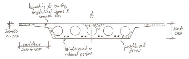
Box girder bridges (Figure 4) have a more efficient section compared to the slab and rib bridges. They represent a very good solution for many sites with a clean aesthetic feel. However, they are made from very complex cross-section, hence the internal shape of the box does cause issues with the concreting procedure during construction. For highway bridges, typical spans range from 30-80m and span to depth ratios within the range of 16-22 is employed for preliminary sizing1. Where a scaffold system is the preferred choice of falsework, then they are best suited for sites over land, if a gantry system is possible then they can be suited for all sites whether inland or outland. The minimum slab thickness utilized is in the range of 200 -250mm. In box girders, the top slab is primarily governed by transverse bending effects from traffic, and therefore the slab thickness increases over the webs.
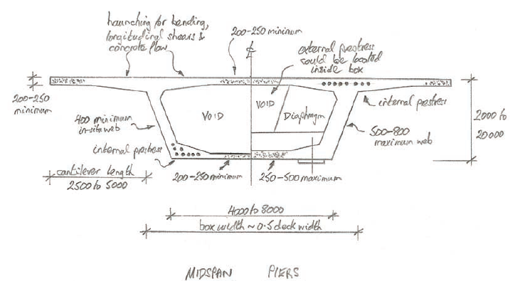
Increased web thickness is generally positioned at about ¼ points of the deck width. Typical rules of thumb for a highway bridge would show a top slab thickness over the webs of (cantilever length)/8 or (box width)/16-18, both of which generate about the same figure. This increased thickness helps the flow of concrete during casting, and is also a means of creating an area at the top of the webs where internal cables can be located. The haunching of the slab also controls longitudinal shears. The variable depth of the top slab therefore serves multiple purposes, though the longitudinal compressions in the top slab at midspan rarely govern this thickness, as the deck width is invariably sufficient to control these stresses.
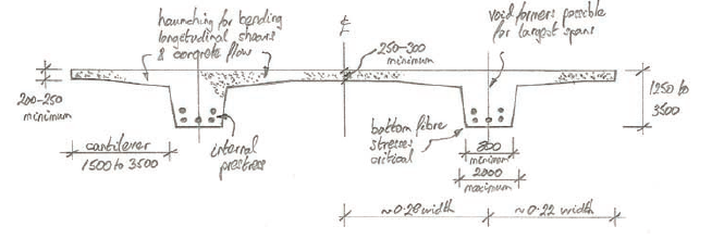
Ideally, the webs of the box are vertical, albeit inclined webs are much more elegant. The shape of the box when inclined is also particularly important because it can mean that the width of the bottom slab is reduced which is beneficial in terms of self-weight reduction as the bottom slabs rarely needs to be as wide as the top slab. The minimum thickness of cast in place box girders is 400mm1. Web thickness is governed by shear and torsion at the pier locations, in which the thickness can increase to 500-800mm2. The only requirement for the bottom slab at midspan is to close the torsion box, hence they can be made as narrow and slender as the code provides. Diaphragms, if ever required is only at the pier locations.
Box girders with single cells are the easiest form to create. They can accommodate widths up to 20m. Occasionally there would be need for maintenance, hence boxes are usually provided with internal access, this means that they should be at least 2m deep. Multi-cell boxes are a nuisance for the construction process, they are too awkward to construct owing too many concrete pours required and difficulties in operating the many internal shutters. They also have tendencies to produce sections with too much web and bottom slabs, resulting in an inefficient self-weight and pre-stressing. Multi-cell boxes should be avoided wherever possible.
Similar to the slab and rib bridges, box bridges are usually cast span by span. Where the bridge is having shorter spans, timber forms supported on scaffolding would be used. As must have being noticed, box bridges are quite rare, as the box section has to be cast in two or even three phases; generally bottom slab and webs, followed by top slab. It is in fact quite difficult to move the long lengths of internal shutter that form the inside of the box, making the operation slow and more expensive.
However, in terms of concreting and pre-stressing, the deck is very economical due to the excellent eccentric load distribution and section efficiency.
Balanced Cantilever Bridges
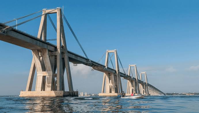
With a balanced cantilever bridge construction, the issues related to casting long length of box are resolved by casting in short lengths. Typical spans range from 40-300m and by definition, are always continuous (Figure 5). Span to depth ratios for highway bridges are typically 18-20 for constant depth schemes1. However, variable depth is very common and would generally be a necessity for all spans over about 60m1. In this case, span to depth ratios for highway bridges are typically 12-18 at the pier locations and 25-40 at midspan1. The balanced cantilever uses a box section that is cast within a travelling formwork/falsework known as a ‘traveller’. There must at least be a minimum deck area of 3000m2 to justify the use or procurement of a traveller and to simplify the formwork the bridge should be made to have constant width.
The aesthetics are very good, particularly with variable depth girders and inclined webs. This method is well suited to all sites, especially ones with poor access from below. Cast in place balanced cantilever bridges are used extensively worldwide and are ideally suited to the typical 3-span or 5-span crossings of a river – locations where the cost of conventional falsework can be prohibitive. The sizing of the box girder is as described previously. The section is again best developed as a single-cell box, with each 3-5m long unit poured in one complete operation. The maximum box width is also about 20m but the minimum box depth is now 2.5m to allow easy use of the internal formwork2.
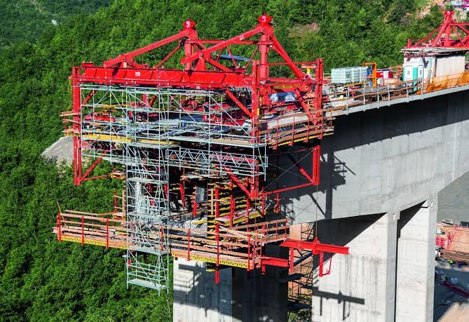
Just like box bridges constructed span – span, inclined webs are considered much more elegant and often used due to the aforementioned advantages. In a balanced cantilever construction, each pair of units is cast either side of the pier location – typically on a weekly cycle – to create a balanced cantilever (Figure 6). Formwork are generally supported from an overhead traveler attached to the end of the last unit. The formwork is usually made up of plywood which allows about 10-59 unit to be casted.
Underslung travellers can also be used, they allow the unit reinforcement cage to be prefabricated and lifted in a single piece. This implies that the casting cycle can be reduced to less than a week, albeit at the cost of a more expensive traveller. In many cases, the pair of units is cast on a Friday and left to cure over the weekend, allowing the deck to be prestressed on the following Monday. The travellers can then be moved forward on Monday afternoon. Cantilevering prestress is applied to each balanced pair until the whole cantilever is complete
Each construction cycle is handled by a composite gang of labour, involved with all the traveller operations, rebar fixing, stressing and grouting, with additional labour used for the weekly concreting phase. Since each traveller is a mechanized piece of formwork/falsework, it must be operated with careful sequence of forming, casting, striking and moving. There are many operations in each cycle, which require a thorough set of checking and signing-off procedures to ensure safe use.
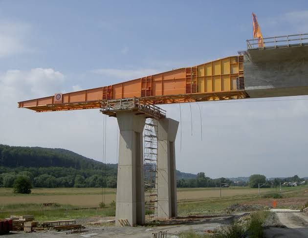
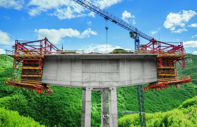
Generally, construction starts from the top of a pier with a 4-12m long hammerhead unit that is cast on a falsework system that sits on the permanent foundations or is supported off the piers. This unit then forms the initial platform for the travellers (Figure 7) while temporary props are employed in providing stability to the balanced cantilever until further continuity of the spans is achieved. Once two cantilevers meet at midspan, a stitch unit is poured to close the span. The same travellers are used to form this stitch unit, though additional falsework is also required to hold the cantilever ends stable during the pour. Once continuity is made and the stitch concrete is up to strength, further pre-stressing cables are added and stressed across each span to make the bridge continuous. Similarly, end span units are cast to reach the abutments, thus completing the whole bridge length.
Perhaps the biggest benefit of employing a cast in place balanced cantilever construction is the use of a bespoke travelling formwork system that can be used as many times on a regular production cycle without the need for building falsework from the ground. The use of a traveller also means that construction can start at several piers at the same time thus reducing the programme duration. The deck is economical in terms of concrete and pre-stressing. Thus, they deliver a very competitive construction cost.
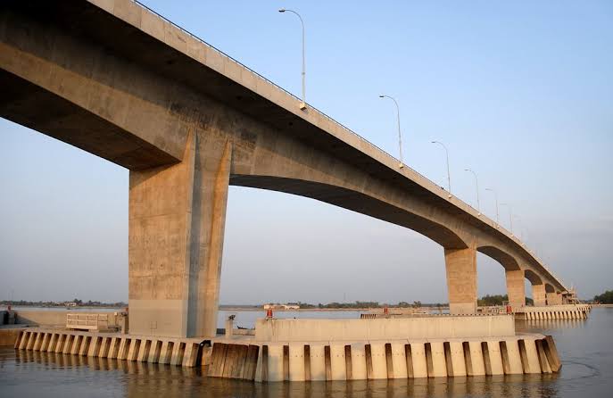
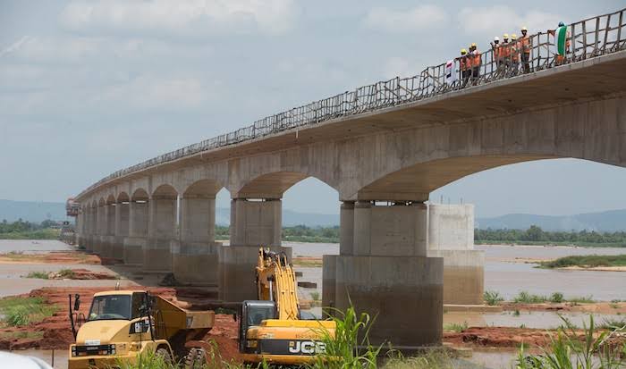
The second Niger bridge under construction in Nigeria employs the balanced cantilever construction method (Figure 8).
Various types of casts in place construction of concrete bridges have been described, which allow both the smallest and simplest slab bridges, and the biggest and most complex beam bridges in the world, to be built. In the next article in the series, we’ll examine more precast bridge types in greater detail.
Sources & Citations
- Concrete Bridge Development Group (2014) ‘Concrete Bridge Design & Construction Series No. 6: construction bridge construction method -in situ’, The structural engineer, 92(6).
- Concrete Bridge Development Group (2014) Technical Guide No. 14: Best construction methods for concrete bridge decks, Camberley, UK: CBDG (publication in 2014)
- Concrete Bridge Development Group (2014) ‘Concrete Bridge Design & Construction Series No. 14: Best construction methods for concrete bridge decks Camberley, UK: CBDG (publication in 2014
- S. Bourne (2019) ‘An Introduction to Bridges for Structural Engineers (part 1)’, The structural engineer, 97(1).
Thank You!