Introduction
Notional loads are horizontal forces added to a structure to account for the effects of geometric imperfections and inaccuracies introduced during its construction. It is the minimum lateral force that must be resisted by a structure in order to ensure stability in the event of geometric imperfection in a structural element. The application of notional loads is meant to serve as an alternative to modelling the actual ‘out of plumbness’ and ‘lack of straightness’ of the structure. Thus, instead of changing the geometry of the structure, an equivalent de-stabilizing load is added to the structure. Perhaps, one of the benefits of handling this issue with loads rather than geometry is that, it is easier and quicker to adjust the loading on structures than modify their stiffness matrix.
This article is concerned with the derivation and application of these notional loading, which is classified as Equivalent Horizontal Forces within the Eurocodes. The article also illustrates how the notional horizontal loads are incorporated into the design process.
Principles
As stated in the last section, notional loads are horizontal forces that must be added to a structure to account for the effect of inaccuracies and imperfections. These imperfections could occur due to either, out of plumpness of columns or out of straightness of elements within the structure. Whatever the case, this effects must be accounted for within the structural analysis and design of the structure. This is done using equivalent horizontal forces. This equivalent horizontal forces are normally considered as a proportion of the vertical forces.
Since notional loads represent forces that are due to imperfections, some materials will be more susceptible to the phenomena than others. For this reason, notional loads are linked to the material the structure is being constructed from.
The Eurocodes for steel and concrete structures have sections within them that are dedicated to deriving notional horizontal loads within structures. The next section will explain how notional loads are applied to steel and concrete structures in the Eurocode.
Application of Notional Loads to Steel Frames
Steel frames are very sensitive to notional loads. Rightly so, most steel frames are composed of prefabricated elements, inaccuracies and eccentricities within their connections are inevitable and very impactful. Consequently, their effect must be considered when designing steel frames.
Clause 5.3.2
This coefficient is defined as:
\phi ={ \phi }_{ o }{ \alpha }_{ h }{ \alpha }_{ m }(Øo) is defined as the sway angle at which a structure rotates due to the application of a notional load. It has a constant value of 0.005
αh is a factor related to the storey height of the vertical elements in the structure, defined as:
{ \alpha }_{ h }=\frac { 2 }{ \sqrt { h } } \quad but\quad 0.66\le { \alpha }_{ h }\le 1‘h’ is the height of the structure
αm takes into account the numbers of vertical elements in a row and is defined as
{ \alpha }_{ m }=\sqrt { 0.5\left( 1+\frac { 1 }{ m } \right) } ‘m’ is the number of vertical elements in a row
The equivalent horizontal load is applied at each floor level and is defined as:
{ F }_{ h }=\phi { V }_{ ED }Where: ‘Fh‘ is the equivalent horizontal load and ‘VEd‘ is the vertical load on a floor. Ø is as defined earlier
Where the overall applied lateral load is more than 15% of the vertical load in a member then the notional horizontal load can be ignored. This is expressed as Hd ≥ 0.15 Vd as defined in the above referenced clause.
Clause 5.3.2(4)B in BS EN1993:1-1
Application of Notional Loads to Concrete Frames
The approach to imperfections in concrete frames is almost the same as with steel frames. The only key difference is that there is some provision for horizontally aligned elements as well as those that are vertical.
Clause 5.2.(5) of BS EN1992-1-1 deals with imperfections in concrete frames using a coefficient (Ѳ) in similar fashion to steel frames, the equivalent load is also function of the vertical force on the structure. However, there is a slight difference in the calculation of this coefficient for concrete frames which takes into account the length of elements as well as their height.
Here, Ѳ is defined as:
\theta ={ \theta }_{ o }{ \alpha }_{ h }{ \alpha }_{ m }(Ѳo) is defined as the sway angle the same way for steel structures Ѳo=0.005
αh is a factor related to the length or height of the vertical elements in the structure, defined as:
{ \alpha }_{ h }=\frac { 2 }{ \sqrt {l} } \quad but\quad 0.66\le { \alpha }_{ h }\le 1‘l’ is the length or height of the elements within the structure
αm is as defined in the case of steel frames. ‘m’ is the number of vertical elements contributing to the horizontal force that is being exerted on the structure, defined as:
{ \alpha }_{ m }=\sqrt { 0.5\left( 1+\frac { 1 }{ m } \right) } The equivalent horizontal load, applied at each floor levels is defined as:
{ F }_{ h }=\theta { V }_{ ED }Notional Loads on Isolated Elements within a Frame
The notional loading due to imperfection discussed in the preceding sections are those occurring in the structure due to irregularities in the frame, known as global imperfections. It is possible for geometric imperfections to also exist within individual elements, this must also be checked. However, these imperfections are usually considered in the design of the elements themselves and are not necessarily assessed as equivalent horizontal loads.
Worked Example
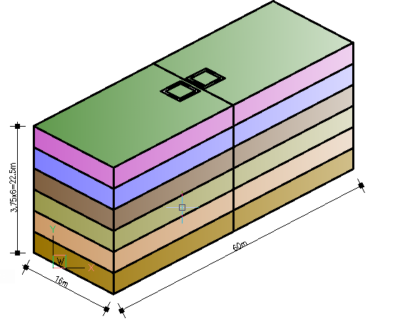
A 6-storey office building is to be constructed using a steel frame structure having a 7.5m x 8m grids layout. The design wind load on this building is 3.5kN/m2 and the design value of the vertical actions on the floors is 14.5kN/m2 while the roof loading is 8.5kN/m2. The structure is being braced using steel bracing and has a movement joint at 30m. Figure 1 shows the overall dimensions of the structure. Determine whether a notional load should be applied to this structure and if so, what is their magnitude.
We are going to first determine the need to include notional loading in the analysis of this frame. This is done by comparing the total applied horizontal load due to wind load in both directions against 15% of the vertical load’s at each level.
Wind Load
The wind load on the structure is defined as:
{ W }_{ k }={ q }_{ w }{ A }_{ ref }Where Wk is the wind load;
Wind load acting on longer side
This is the wind load acting on the bracing in the shorter direction of the structure.
{ W }_{ k }=3.0\times (22.5\times 30)=2025kN@ Roof=\frac { 3.75\times 0.5 }{ 22.5 } \times 2025=168.7kN@Floors =\frac { 3.75 }{ 22.5 } \times 2025=337.5kNWind load acting on shorter side
This is the wind load acting on the bracing in the longer portion of the structure.
{ W }_{ k }=3.0\times (22.5\times 16)=1080kN@Roof =\frac { 3.75\times 0.5 }{ 22.5 } \times 1080=90kN@Floor =\frac { 3.75 }{ 22.5 } \times 1080=180kNVertical Loads
{ V }_{ Ed }=qAWhere: VEd is the vertical load per level; q is the level design load; A is the area of the structure
Roof Level
{ V }_{ Ed }=8.5\times (30\times 16)=4080kN0.15{ V }_{ Ed } =0.15\times 4080=612kNFloor Levels
{ V }_{ Ed }=14.5\times (30\times 16)=6960kN0.15{ V }_{ Ed }=0.15\times 6960=1044kNVerification
@Roof:612kN>168.7kN
\& \quad 612>90kN
@Floor :1044kN>337.5kN
\& \quad 1044>180kN\\
Therefore notional horizontal load must be considered in both directions.
Equivalent Horizontal Forces
{ F }_{ h }=\phi { V }_{ ED }\phi ={ \phi }_{ o }{ \alpha }_{ h }{ \alpha }_{ m }{ \phi }_{ o }=0.005{ \alpha }_{ h }=\frac { 2 }{ \sqrt { h } } =\frac { 2 }{ \sqrt { 22.5 } } =0.42\ge 0.66=0.66
{ \alpha }_{ m }=\sqrt { 0.5\left( 1+\frac { 1 }{ m } \right) } =\sqrt { 0.5\left( 1+\frac { 1 }{ 15 } \right) } =0.73\phi ={ \phi }_{ o }{ \alpha }_{ h }{ \alpha }_{ m }=0.005\times 0.66\times 0.73=0.0024
Therefore the equivalent horizontal force to be applied at each level is 0.24% of the vertical loads applied at the level.
{ F }_{ h,roof }=\phi _{ Ed }{ V }_{ Ed }=0.0024\times 4080=9.8kN
{ F }_{ h,floors }=\phi { V }_{ Ed }=0.0024\times 6960=16.70kN
Finally, this load must be added to the wind loads in both directions when assessing the structure for lateral loads. Consequently, the load is shared by the lateral stability system according to their stiffness’s.
See: Assessing the Stability of Frames
Thank You!!!
best pharmacy prices for cialis – cialis 5mg tablets buy cialis online free shipping
buy sildenafil 100mg uk – viagra online cheap viagra prescription online
generic cialis daily canada – buy cialis professional 20 mg cialis cheapest price canada
ivermectin 3mg tablet – buy liquid ivermectin stromectol generic name
online slots real money – casino betfair casino online
cure ed – natural ed pills for him ed pills
buy prednisone online paypal – prednisone 5 mg prednisone in india
ivermectin 2 – ivermectin topical ivermectin oral
erectile dysfunction exercises – ed treatment drugs ed pills that work
ventolin tablet price – ipratropium albuterol ventolin inhaler
cytotec pills online – cytotec prescription uk buy cytotec online canada
doxycycline purchase uk – doxycycline over the counter australia 2985 doxycycline
price of neurontin – buy generic neurontin online levothyroxine 80 mcg
sildenafil 50 mg tablet cost – generic viagra prescription online
cialis 2.5mg – cialis prescription discount brand name cialis online
buy vardenafil 10mg – acheter vardenafil buy vardenafil
ivermectin cream 1 – ivermectin for cov 19 cost of ivermectin lotion
india buy prednisone online – prednisone 10 mg canada prednisone 20 mg
accutane cost – accutane india pharmacy generic accutane price
buy amoxil – amoxclin buy amoxicillin 500 mg canada
20 mg generic sildenafil – Generic viagra us viagra 4 tablet
buy cialis 20mg online canada – Cialis samples best place to buy cialis online
how to buy stromectol – ivermectin generic name ivermectin cream
medicine prednisone 10mg – discount prednisone 10 mg prednisone 10 mg coupon