This article discusses the theoretical basis of column buckling, emphasizing Euler’s formula for idealized conditions and modifications for real-world applications.
Steel columns are vital load-carrying elements in structures, supporting axial compressive forces and transferring them to foundations. Their design requires careful attention to stability, as failure due to buckling can lead to catastrophic consequences. A comprehensive understanding of the buckling phenomenon, slenderness effects, and practical considerations is essential to ensure structural safety and performance.
Buckling, a mode of instability, occurs when a column subjected to axial compression reaches a critical load and undergoes lateral deformation. Unlike yielding, which depends on material strength, buckling is primarily influenced by geometry, boundary conditions, and load eccentricities. Engineers must consider these factors in analysis and design to prevent instability.
This article discusses the theoretical basis of column buckling, emphasizing Euler’s formula for idealized conditions and modifications for real-world applications. We will also explore practical considerations, design codes, and a detailed worked example, providing a complete understanding of column stability.
Theoretical Foundation of Buckling
Buckling is a failure mode where structural elements deform laterally under compressive loads, even before the material reaches its yield strength. Euler’s buckling theory forms the cornerstone for understanding this behavior in ideal columns. According to this theory, the critical load, Pcr at which buckling occurs is expressed as:
P_{cr}=\frac{\pi^2EI}{(kL)^2}This formula assumes the column is perfectly straight, homogeneous, and free from imperfections or eccentric loads. Key parameters influencing the critical load include:
Where: Elastic Modulus (E): A measure of the material’s stiffness; Moment of Inertia (I): Indicates the cross-section’s resistance to bending; Effective Length (KL): Represents the buckling length based on boundary conditions.
As the effective length increases, the critical load decreases, highlighting the importance of boundary conditions in verification.
Slenderness Ratio and Classification of Columns
The slenderness ratio, λ=KLr is a dimensionless quantity that characterizes a column’s propensity to buckle. Here, r is the radius of gyration, calculated as:
r=\sqrt\frac{I}{A}Columns can be categorized into three types based on their slenderness ratio:
- Short Columns: These fail due to material yielding under compressive loads. Buckling does not govern their behavior.
- Intermediate Columns: Experience a combination of yielding and buckling. Their failure mode depends on both material and geometry.
- Slender Columns: Buckling dominates their failure mechanism. The critical load is governed by the column’s geometry and boundary conditions.
A higher slenderness ratio indicates a greater tendency to buckle, requiring stricter design considerations to ensure safety.
Boundary Conditions and Effective Length
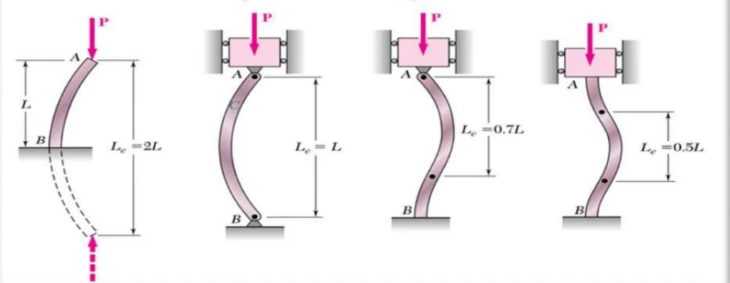
Boundary conditions, which describe how a column is supported at its ends, significantly affect buckling behavior. Different support configurations alter the column’s effective length, KL, as follows:
- Pinned-Pinned: Both ends are free to rotate but restrained against lateral movement (K=1.0).
- Fixed-Fixed: Both ends are restrained against rotation and lateral movement (K=0.5).
- Fixed-Free (Cantilever): One end is fixed, while the other is free (K=2.0).
- Fixed-Pinned: One end is fixed, and the other is pinned (K = 0.7).
The effective length directly influences the critical load. Shorter effective lengths (e.g., fixed-fixed conditions) result in higher buckling resistance, while longer effective lengths reduce stability.
Imperfections and Eccentricity
In real-world scenarios, columns rarely behave as idealized elements. Imperfections such as initial crookedness, uneven loading, and residual stresses reduce the critical load compared to theoretical predictions, thus additional factors are often applied. Additional factors include:
- Eccentric Loading: Axial loads rarely act perfectly through the centroid, introducing bending moments that amplify instability.
- Residual Stresses: Manufacturing processes like welding and rolling induce stresses that influence buckling behavior.
- Local Buckling: Thin-walled sections may experience localized instability before global buckling occurs.
These factors necessitate the use of safety factors and empirical equations in design codes, ensuring practical designs account for real-world variability.
Advanced Buckling Analysis
Modern structural analysis incorporates advanced methods to predict buckling behavior more accurately. Techniques such as finite element analysis (FEA) allow engineers to simulate column behavior under realistic conditions, including imperfections and complex loading. FEA provides detailed insights into stress distribution, deformation patterns, and potential failure modes.
Design Codes and Provisions
Design codes provide practical guidelines for stability analysis and buckling design. Key provisions include:
- AISC (American Institute of Steel Construction): Introduces column strength curves and interaction equations for combined axial and bending loads.
- Eurocode 3: Employs non-dimensional slenderness, λ and reduction factors for buckling resistance.
- BS 5950: Offers simplified approaches for stability verification, emphasizing practical design considerations.
These codes ensure uniformity in design practices and provide reliable methods for calculating column capacity under buckling.
Worked Example
Design a pinned-pinned steel column with a height of 6 meters, a cross-section of IPE 300 (I=85.5×106 mm4 A = 7860mm2), and a material with E=210 GPa and fy=355MPa. Calculate the critical buckling load and verify its stability using Eurocode 3 provisions.
Calculate Radius of Gyration
r=\sqrt\frac{I}{A} = \sqrt \frac{85.5\times10^6}{7860}=104.5mm: Determine Slenderness Ratio
\lambda=\frac{KL}{r} =\frac{1\times6000}{104.5}=57.4Calculate Critical Load Using Euler’s Formula
P_{cr}=\frac{\pi^2EI}{(kL)^2} =\frac{\pi^2\times210\times10^3\times 85.5\times10^6}{(1\times6000)^2} =1977kNVerify Using Eurocode 3
N_{b,Rd}= \chi \cdot A \cdot f_yThe reduction factor, χ depends on the non-dimensional slenderness, λˉ, and is determined from code-specific charts.
Conclusion
Stability and buckling analysis play a pivotal role in the design of steel columns, ensuring safe and efficient structural systems. An understanding of theoretical principles and incorporating real-world considerations is required for engineers to design columns that resist buckling under various conditions. Modern codes and analysis tools further enhance the ability to create reliable and optimized designs.
See: Lateral Torsional Buckling of Steel Elements
Sources & Citations
- Euler, L. (1744). Additamentum ad deformationem curvarum elasticarum.
- American Institute of Steel Construction (AISC). (2016). Steel Construction Manual, 15th Edition.
- European Committee for Standardization (CEN). (2005). Eurocode 3: Design of Steel Structures.
- Timoshenko, S.P., & Gere, J.M. (1961). Theory of Elastic Stability.