Pile integrity testing provides an important quality-control link between the pile assumed during structural and geotechnical design and the pile actually constructed on site.
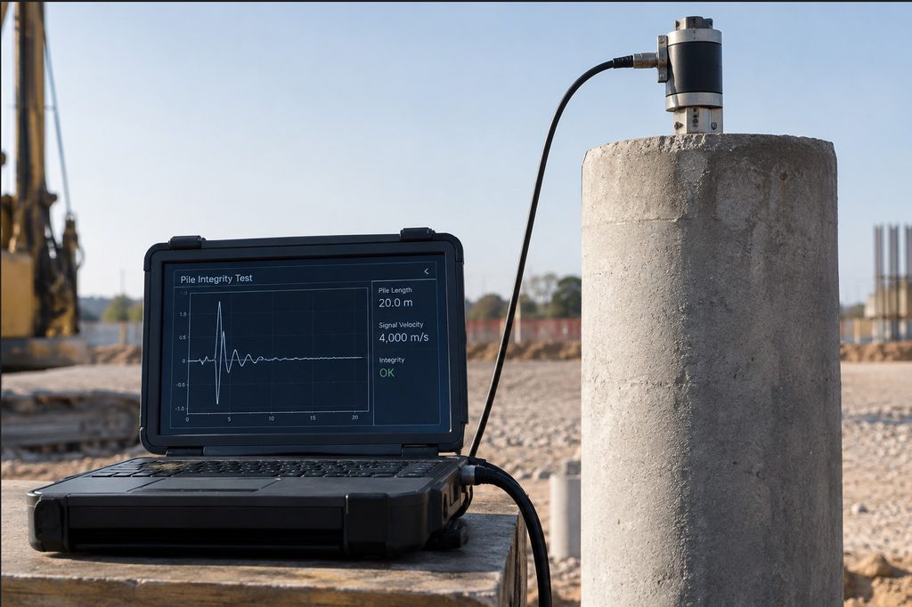
Pile foundations are often designed on the assumption that the completed pile will have a continuous shaft, the specified diameter, adequate concrete quality and the required founding depth. Once a bored pile has been constructed, however, much of the element is hidden below ground. The structural engineer cannot directly inspect the concrete, reinforcement cage or pile-soil interface along its full depth. This creates an important quality-control problem: how can the engineer establish that the constructed pile reasonably corresponds with the pile assumed in design?
Pile integrity testing provides one part of the answer. It uses non-destructive techniques to investigate the continuity, geometry and consistency of a completed pile and to identify features that may indicate defects. The tests are particularly valuable for bored piles, where construction takes place below ground and concrete may be placed through water or drilling fluid. They do not, however, replace pile load testing. Integrity testing primarily investigates the physical condition of the pile, while load testing evaluates its response to applied load.
The distinction is important because a pile can have apparently good integrity but inadequate geotechnical capacity. Conversely, a pile may have an integrity indication that requires investigation without necessarily being structurally unacceptable. The engineer must therefore interpret the test in conjunction with the design, construction records, ground conditions and other test results.
What Is Pile Integrity Testing?
Pile integrity testing is a group of non-destructive testing techniques used to investigate the physical condition of deep foundation elements. Depending on the method, the test can provide information about pile length, continuity, changes in cross-section and variations in the concrete along the pile.
Low-strain impact testing is one of the simplest approaches. A small mechanical impact is applied to the pile head and an instrument measures the resulting response. The impact generates a stress wave that travels down the pile. When the wave encounters a change in the pile’s impedance, part of the wave is reflected towards the pile head. The reflected response is then recorded and interpreted.
ASTM D5882 describes low-strain impact integrity testing as a method for evaluating pile integrity, physical dimensions, continuity and consistency of the pile material. Importantly, the standard also states that the method does not provide information on pile bearing capacity.
This makes the test particularly useful as a construction-quality investigation. It can indicate whether something has changed within the pile, but it does not independently establish that the pile can support the design load.
Low-Strain Integrity Testing
The principle behind low-strain testing is relatively straightforward. If a pile has uniform properties along its length, the stress wave should travel through it with a relatively predictable response and produce a reflection associated with the pile toe.
A significant change in cross-sectional area or material properties can produce an earlier reflection. For example, a reduction in pile diameter can produce an impedance change that may be interpreted as a possible necking zone. An increase in diameter can produce a different reflection pattern. Cracks, inclusions, poorly formed concrete and other discontinuities may also influence the response.
The technique is therefore useful for screening piles relatively quickly. It can be applied to cast-in-place concrete piles and other deep foundation elements that are suitable for low-strain testing. However, interpretation becomes more difficult as pile length increases or where surrounding soil conditions strongly influence the response. A deeper defect can also be masked by a shallower and more significant anomaly. FHWA guidance identifies this limitation when comparing surface stress-wave methods with downhole techniques such as crosshole sonic logging.
The condition of the pile head is also important. A poorly prepared or irregular pile head can introduce noise into the signal. The exposed pile head should therefore be adequately trimmed and prepared before testing. The tester also needs reliable information about the expected pile length, diameter, construction method and concrete properties.
Crosshole Sonic Logging
Crosshole Sonic Logging (CSL) provides a more detailed investigation of concrete within a bored pile when access tubes have been installed during construction. Steel or other suitable access tubes are positioned within the reinforcement cage before concrete placement. After the concrete has hardened, ultrasonic probes are lowered into the water-filled tubes.
A transmitter sends an ultrasonic pulse through the concrete towards a receiver in another tube. The equipment records the travel time and relative signal energy as the probes move along the pile depth. A significant increase in travel time or reduction in signal energy can indicate a zone of potentially poor concrete.
CSL is particularly useful for large-diameter bored piles because the test provides information between the installed access tubes rather than relying only on a response measured at the pile head. ASTM D6760 describes the technique as a method for assessing the homogeneity and integrity of concrete between parallel access ducts. It also notes an important limitation: the test primarily evaluates the concrete between the ducts and therefore may provide limited information outside the region bounded by the tubes.
This is why the arrangement and installation of access tubes matter. A poorly installed tube can compromise the test. The tubes should remain continuous, accessible and properly positioned throughout concreting. Their installation is therefore part of the quality-control process, not merely a requirement for the testing company.
Thermal Integrity Profiling
Thermal Integrity Profiling (TIP) is another method used for assessing the integrity of cast-in-place concrete deep foundations. The technique makes use of the heat released as cement hydrates. Temperature measurements are taken at different depths and locations within the pile, allowing variations in the concrete profile to be assessed.
Unlike low-strain testing, TIP can provide information related to the actual concrete distribution around the reinforcement cage. It can therefore be useful for identifying variations in pile radius, concrete cover and potential anomalies.
FHWA identifies CSL, TIP and Gamma-Gamma Logging among the integrity-testing methods currently used for drilled shafts in transportation infrastructure. The choice of method depends on the foundation type, construction method, project requirements and level of information required.
What Defects Are Engineers Looking For?
The purpose of an integrity test is not simply to produce a pass or fail label. The engineer is looking for evidence of conditions that could affect the structural or geotechnical performance of the pile.
Potential problems include necking, bulging, soil or drilling-fluid inclusions, poor-quality concrete, voids, cracks, segregation and discontinuities caused by interruptions during concreting. A defect may also result from movement of the reinforcement cage or problems during tremie placement.
For example, consider a bored pile constructed through unstable ground. If the borehole wall collapses locally before or during concreting, soil may enter the fresh concrete. The resulting inclusion could create a local reduction in concrete quality or effective pile area. Similarly, if the tremie pipe is not maintained at an appropriate embedment within the fresh concrete, contaminated material may enter the pile.
This is why the integrity test should never be considered separately from the construction record.
Worked Example: Estimating the Depth of an Indication
Consider a 600 mm diameter bored pile with a designed length of 20 m. A low-strain integrity test is performed after the pile head has been prepared.
Assume the interpreted compression-wave velocity through the pile is:
During the test, a significant reflection occurs at a measured round-trip time of:
For a reflection from a feature within the pile, the wave travels from the pile head to the feature and then returns to the head. The approximate depth of the reflecting feature can therefore be estimated from:
Converting the measured time:
Therefore:
The indication is therefore approximately 13 m below the pile head.
This calculation does not mean that a defect definitely exists at 13 m. It only establishes the approximate location associated with the reflected response. The engineer must examine the shape and magnitude of the signal and consider the expected toe reflection, pile dimensions, soil profile and construction history.
Suppose the concreting record shows that the pile experienced a significant interruption when the concrete level was approximately 12–13 m below the working platform. The test indication would then deserve particular attention because the independent construction record provides a plausible explanation for the anomaly.
This illustrates an important principle in integrity testing: the test result becomes much more useful when it is interpreted alongside construction information.
Importance of Construction Records
Pile integrity testing should be viewed as part of a broader quality-assurance process rather than as an isolated activity after construction.
For each bored pile, the contractor should maintain records of the pile diameter, drilled depth, reinforcement cage installation, groundwater or drilling-fluid conditions, concrete grade, concrete delivery times, concrete volumes and concreting duration. The record should also identify interruptions, unusual ground conditions and any difficulties encountered during drilling or concrete placement.
Concrete volume is particularly useful when investigating a suspected pile defect.
For the 600 mm diameter, 20 m long pile used in the previous example, the theoretical geometric concrete volume is:
The actual concrete volume should normally exceed the theoretical volume because of construction tolerances and ground conditions. However, an unexpected departure from the anticipated volume can provide useful evidence.
If only 5.0 m³ of concrete was recorded, the engineer would have reason to investigate. Conversely, if 8.0 m³ was placed, this could indicate an enlarged bore, overbreak or other ground-related condition. Neither result alone proves that the pile is defective, but both should prompt the engineer to review the construction information.
What Happens When a Pile Shows an Anomaly?
An integrity indication should not automatically result in pile rejection. The appropriate response depends on the nature, location and severity of the indication and its potential effect on the pile’s required performance.
The first step is normally to review the test data and compare the result with the pile construction records. Similar piles constructed under comparable conditions should also be considered. Where the indication is significant, supplementary testing may be required.
For a bored pile with CSL access tubes, CSL can provide additional information about the concrete between the tubes. In other situations, coring, additional non-destructive testing or a load test may be appropriate. ASTM guidance for crosshole testing recognises that further investigation may be necessary where a potentially defective zone is identified.
The final decision should therefore come from the responsible engineer based on the evidence available. A testing technician’s description of an anomaly is not, by itself, a structural assessment.
Testing Cannot Replace Good Pile Construction
The most effective approach to pile integrity is to control the construction process from the beginning.
For bored piles, this means maintaining the stability and cleanliness of the bore, controlling reinforcement cage installation, using an appropriate concrete mix, maintaining proper tremie procedures and avoiding unnecessary interruptions during concrete placement.
The concrete volume should be monitored against the theoretical pile volume. Delivery tickets should be retained. The depth and condition of the bore should be recorded. Where integrity access tubes are required, they should be installed and protected correctly before concreting.
These measures make the subsequent test result much easier to interpret.
A pile integrity test can reveal an unexpected condition, but it cannot reconstruct a poor construction record. Good records allow the engineer to connect the test response with what actually happened during construction.
Conclusion
Pile integrity testing provides an important quality-control link between the pile assumed during structural and geotechnical design and the pile actually constructed on site. Low-strain testing, crosshole sonic logging and thermal integrity profiling each provide different types and levels of information, with corresponding limitations.
Thus, the engineer should therefore resist the temptation to treat integrity testing as a simple pass-or-fail exercise. A reflected wave, a reduction in ultrasonic signal or a temperature anomaly is an indication requiring engineering interpretation. The significance of that indication depends on the pile geometry, defect location, construction method, ground conditions and structural demand.
Most importantly, integrity testing does not replace proper construction control or pile load testing. Its greatest value comes when testing, construction records and engineering judgement are used together.
And for deep foundations, the objective is not merely to prove that a test was completed. The objective is to establish reasonable confidence that the pile constructed below ground is capable of performing the function for which it was designed.
Also See: Geotechnical Design of Concrete Piles to EC7 | Worked Example
Sources & Citations
- ASTM International. ASTM D5882: Standard Test Method for Low Strain Impact Integrity Testing of Deep Foundations.
- ASTM International. ASTM D6760: Standard Test Method for Integrity Testing of Concrete Deep Foundations by Ultrasonic
- Crosshole Testing. ASTM International. ASTM D7949: Standard Test Methods for Thermal Integrity Profiling of Concrete
- Deep Foundations. Federal Highway Administration. Geotechnical Engineering Circular No. 15 (GEC 15): Load and
- Resistance Factor Design (LRFD) for Deep Foundations. Federal Highway Administration.
- Drilled Shafts: Construction Procedures and Design Methods, FHWA-NHI-10-016.
