This article discusses the various types of loading on box culverts and how to estimate the design value of these loads based on the recommendations of the Eurocodes.
Before commencing with the specifics of a culvert’s design, a clear understanding of the variety and intensity of loads likely to impact the structure is essential. This foundational principle stems from the fact that, aside from the hydraulic dimensioning aimed at accommodating the volume and flow of water, the magnitude and frequency of loads exerted upon the culvert are critical determinants of its overall structural integrity.
Determining these loads is a multi-step process that typically involves the assessment of both dead loads, such as the weight of the culvert structure itself and any permanent features on or around it, and live loads, which may include transient forces from vehicular traffic, pedestrians, or animals crossing over the culvert. Thus, the size of the culvert elements—ranging from the width and height of the culvert’s opening to the thickness and composition of its walls and slabs—is thus directly influenced by the load analysis.
Design codes and standards offer guidance on the minimum requirements for these loads. The Eurocodes specifically, outlines procedure for determining these loads which involves meticulous calculations of traffic loadings; the self-weight of the box culvert; lateral forces and vertical forces from soil etc. This article discusses the various types of loads on box culverts and how to estimate their values.
Types of Loads on Box Culverts
The loads applied on box culverts are integral considerations in their structural design, with a clear distinction between permanent actions and variable actions. These load categories play a crucial role in shaping the overall performance, safety, and durability of box culverts.
Permanent Actions
Permanent actions encompass forces that remain constant and exert a continual impact on the box culvert. These include:
Dead Loads
Dead loads constitute the inherent weight of the box culvert components, such as base slabs, walls, and top slabs. To estimate dead loads, the density of concrete is applied thickness of the culvert element.
Superimposed Dead Loads
The Superimposed dead loads involve additional permanent fixtures or structures placed on the culvert. These include any weight of earth fill or asphaltic layer on the top slab.
Horizontal Earth Pressure
The primary function of the culvert wall is to hold back surrounding soil. The implication is that this surrounding soil exerts a horizontal earth pressure, and the magnitude of this horizontal pressure must be estimated and added to the list of loads on the culvert. To estimate the horizontal pressure on the wall, we simply apply the coefficient of at rest pressure to the base density of the surrounding soil.
Hydrostatic Pressure
Should the culvert be full, hydrostatic pressure due to moving water tends would be exerted on the culvert walls. However, this tends to be a beneficial loading condition, hence the value is mostly ignored during load estimation and analysis.
Variable Actions
Variable actions encompass forces that fluctuate or depend on specific conditions. These include:
Traffic Loading
One of the primary and perhaps the most important variable actions applied on culverts is traffic loading. Traffic loading represents the dynamic forces induced by vehicular traffic unto the culvert. BS EN 1991-2:2003 Actions on Structures – Part 2: Traffic Loads on Bridges sets out a series of load models that should be considered in estimating traffic loads. For culverts, three Load Models (LM1-LM3) are applicable. In applying the load model, the box culvert structure is divided into notional lanes.
- Load Model 1 – Concentrated and Distributed Load
- Load Model 2 – Single Axle Loads
- Load Model 3 – Crowd Loading
Where a culvert structure is less than 5m, LM3 is not critical and could be ignored.
A very important aspect of applying traffic load as to do with dispersal. Where a culvert is buried, the traffic loads are not in direct contact with the culvert, therefore they are dispersed through the fill to the top slab. This is generally done by utilizing the load increment method or Boussinesq’s equation. However, where the culvert is otherwise not buried or the thickness of the fill is less than 600mm, load dispersal is not necessary, and the traffic load can be considered to be applied directly on the culvert.
Surcharge Loads
Surcharge loads refer to transient forces imposed by additional materials or loads placed on top of the culvert. Understanding and accounting for surcharge loads are crucial to prevent overloading and ensure the culvert’s resilience.
Temperature Load
The effects of temperature variations on the structure are considered variable actions. Proper analysis is necessary to address thermal expansion and contraction, ensuring the longevity of the box culvert under different temperature conditions. This is determined using BS EN 1991-1-5:2003 and Clause NA.2.2.1(b)
Breaking and Acceleration
Dynamic forces induced by breaking and acceleration, particularly relevant in the context of vehicular traffic, are additional variable actions that engineers must consider. Designing culvert to withstand these dynamic forces is vital for overall safety and performance. Breaking and acceleration forces can be estimated using Clause 10.2.8.2 of PD 6694-1:2011.
Worked Example
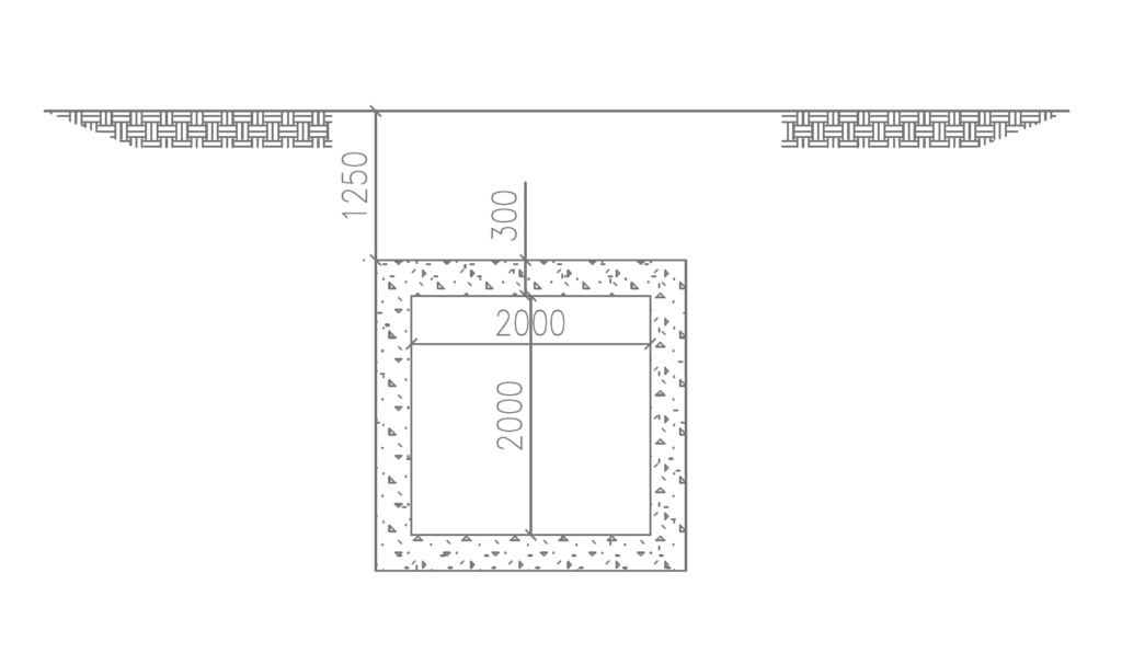
Determine the load on a culvert in a roadway corridor using the following parameters. The top slab of the culvert is required to sustain a fill of 1.25m thick fill on the culvert before the carriageway and an asphaltic layer of 75mm. The culvert has a carriageway of 7.3m. The width of the culvert walls is 3.0m and the thickness of the culvert is 300mm. Assume the backfill soil has an internal friction angle and base density of 30° and a base density of 18kN/m³, the unit weight of asphalt concrete is 22kN/m³, and that of reinforced concrete is 25kN/m³.
Permanent Actions
The permanent actions on the culvert are of two types – vertical and horizontal. vertical permanent actions include loads due to the self-weight of the slab, earth fill and the asphaltic layer. While the horizontal permanent actions arise from the lateral earth pressure on the culvert walls.
Vertical Permanent Actions
1. Self-weight of top slab
=0.3\times 25 = 7.5kN/m^2
2. Weight of earth fill
= 1.25\times 18 =22.5kN/m^2
3. Asphaltic layer
=0.075\times22=1.65kN/m^2
For the purpose of simplicity, we can combine these actions such that the vertical permanent action on the box culvert is given by:
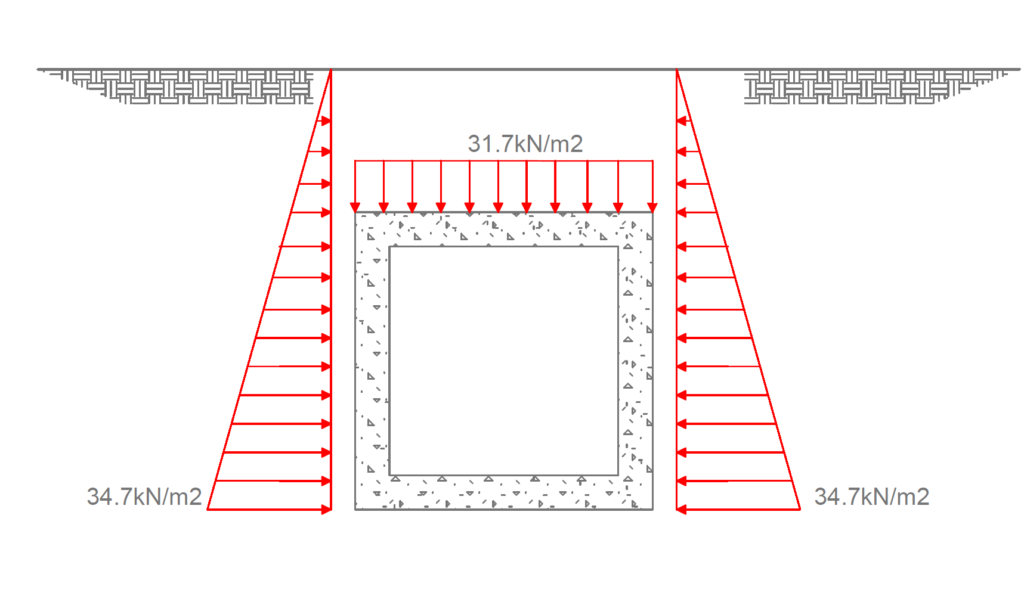
g_{k,v}=7.5+27+1.65=31.7kN/m^2Horizontal Permanent Actions
The horizontal permanent actions are basically from the lateral earth pressure on the surrounding soil around the box culvert.
k_o =1-sin\phi =1-sin30=0.5
Lateral earth pressure
k_o\gamma_sh =0.5\times18\times(2.6+1.25)\\= 34.65kN/m^2
g_{k,h}=34.65kN/m^2Variable Actions
Only two types of variable actions will be considered here: vertical traffic loading and the lateral load due to surcharge. While other variable actions from temperature, braking, and acceleration are equally important, they do not produce such unfavorable actions to control the design. Hence, they are ignored here. However, the reader may find useful guides in the sources and citations part of this article.
Traffic Loding
Since the culvert width is less than 5m, we are going to consider only load models LM1 and LM2.
Load Model 1: UDL + Tandem Systems
To apply Load Model 1 (LM1) we must divide the culvert into the recommended notional lanes.
Notional lane width = 3m
Number of notional lane:
n=int(w/3)=int(7.3/3)=2
Width of remaining area:
7.3 -(3\times2)=1.3
Therefore, we can determine the UDL and concentrated loads on the various lanes.
For lane 1:
udl_{lane,1}=\alpha_{q1}q_{1k} =0.61\times9 =5.5kN/m^2TS_{lane,1} = 300kNFor lane 2:
udl_{lane,1}=\alpha_{q1}q_{1k} =2.2\times2.5 =5.5kN/m^2TS_{lane,1} = 200kNRemaining area:
udl_{lane,1}=\alpha_{q1}q_{1k} =2.2\times2.5 =5.5kN/m^2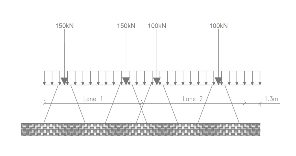
Figure 2 shows the application of LM1 on the carriageway. We are however required to disperse this load to the box culvert since the fill is greater than 600mm. In dispersing this load, the UDL is not considered. Clause 4.9.1 (Note 1) of EN 1991-2:2003 recommends a dispersal angle of 30° to the vertical for a well-compacted earth fill. Contact area of the load = 400 x 400
By inspection of figure 2, we see that the wheel in the axles overlap when considering the tandem loads. Thus, we must first of all determine the load in the dispersal zones before we determine the patch load for each axle.
Width of dispersed area of the box culvert:
400+2\times1250tan30=1843
Therefore, dispersed area of box culvert = (1843 x 1843mm)
Having obtained the dispersed area, the load per square meter where dispersion overlaps is given as:
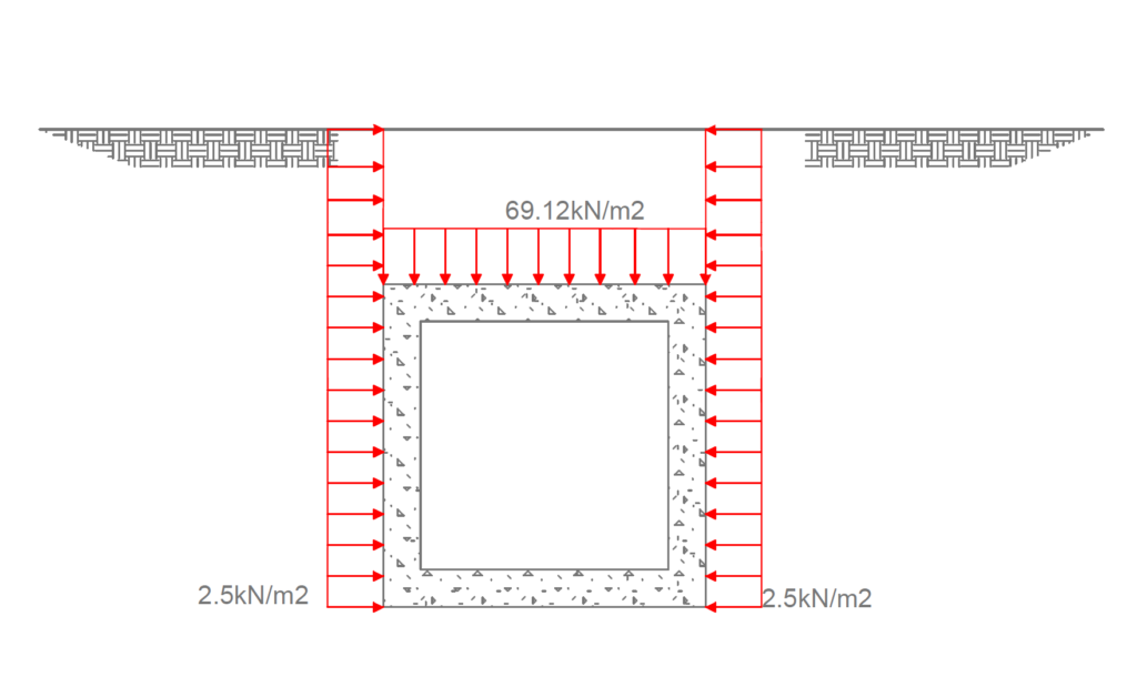
=\frac{bW_1}{L^2}+\frac{aW_2}{L^2}\frac{1\times150}{1.84^2} +\frac{(1.84-1)\times100}{1.84^2}=69.12kN/m^2Load Model 2
We can also consider load model 2 by utilizing figure 2. Wheel load = 200kN; contact patch area = 400 x 400 and the wheel of spacing on axle =2.0m. Since the width of our contact area is less than the spacing of the axle, the dispersal zones do not overlap. Thus, patch load on box culverts is given as:
=\frac{200}{1.84^2} = 59.07kN/m^2An inspection of the traffic loads shows that the magnitude of LM1 is more, therefore this would likely produce a more onerous result during analysis, thus, this will be adopted as the characteristic value of the traffic load on the box culvert.
Surcharge
k_oq=0.5\times5= 2.5kN/m^2
Figures 4 and 5 details the magnitude and direction of the permanent and variable actions on the box culvert respectively.
See: Derivation of Loading on Retaining Structure
- BS EN 1991-2:2003 – Eurocode 1: Actions on Structures – Part 2: Traffic Loads on Bridges
- PD 6694-1:2011 Recommendations for the design of structures subject to traffic loading to BS EN 19971:2004,
Thank you for the good elaboration on loads acting on buried structures particularly box culvert and how to apply Eurocode to analysis the loads for a culvert with cover equal or greater than 0.6m. Can you explain or share with example a design/load analysis of culvert with cover less than 0.6m, and if it is multiple cells e.g two cells I will appreciate. Or you can share through my email any resource with worked examples in such scenario.
Last but not least I appreciate your good work.