This article examines the cause of the collapse, investigates the construction context, and explores the errors made. It also identifies key lessons for engineers, contractors, and clients.
Stadiums symbolize unity, performance, and modern engineering achievement. These iconic structures combine crowd capacity, aesthetics, and structural elegance under challenging design demands. When something goes wrong, the consequences reach far beyond structural damage.
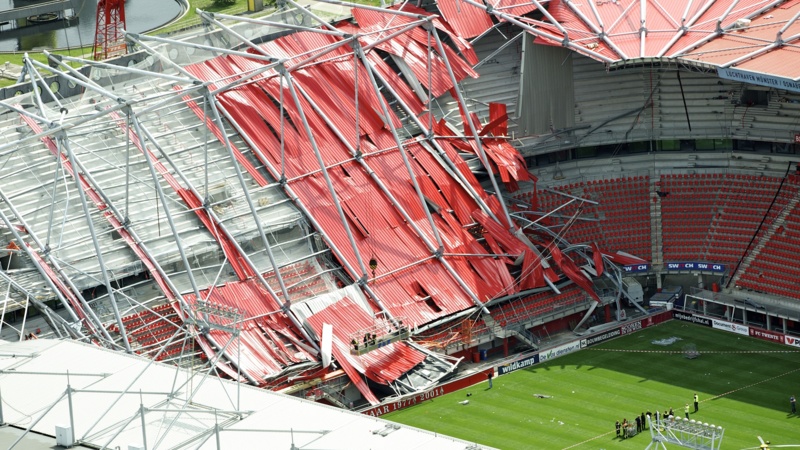
The De Grolsch Veste, suffered a tragic collapse during its roof expansion in July 2011. The accident claimed two lives and injured others. The incident remains a painful but instructive example of what happens when temporary works stability and construction coordination fail.
This article examines the cause of the collapse, investigates the construction context, and explores the errors made. It also identifies key lessons for engineers, contractors, and clients.
The Stadium and Its Ambition
De Grolsch Veste stands in Enschede, Netherlands. It serves as the home ground of FC Twente, a top-tier Dutch football club. The stadium was built in 1998 with an initial capacity of around 13,500 spectators. It featured a modern L-shaped configuration with partial roof coverage.
In 2008, the club undertook a significant expansion to boost capacity to 24,000. Encouraged by success and strong attendance, management announced a second phase of expansion. This phase aimed to add more seating behind one goal, bringing the total capacity to 32,000. The transformation would convert the L-shaped plan to a U-shaped bowl (Figure 1).
To achieve this, engineers designed a lightweight steel roof to extend across the new seating section. The structure included curved roof trusses and cantilevers. Erection methods called for sequential installation from supports near the existing stand, progressing outwards to new columns.
At the time of the accident, most steelwork had been erected. Workers were assembling the final sections when the structure failed.
What Happened During Construction
On July 7, 2011, part of the stadium roof collapsed while under construction. The failure occurred near the corner of the expansion site. The collapse brought down steel trusses, purlins, roof panels, scaffolding, and platforms.
Two workers lost their lives instantly. Several others sustained injuries. Construction came to a halt. Investigators sealed off the site and launched formal inquiries into the cause.
The collapse did not occur during occupancy or a match. This fact prevented a much larger tragedy. However, the impact on public trust and the project timeline proved substantial.
Investigating the Cause of Collapse
Authorities opened a comprehensive investigation into the collapse. Structural engineers, safety experts, contractors, and forensic specialists reviewed documentation, site photos, and witness accounts. The findings centered on several key issues.
First, the structure lacked sufficient temporary stability. The final roof geometry relied on full connection between trusses, purlins, and bracing. At the time of the collapse, several permanent ties had not been installed. Temporary cables and support members, which held earlier parts of the structure, had been removed too early.
Second, site personnel placed additional loads on incomplete steelwork. These included pallets of roofing materials and tools. Some loads were static. Others shifted during lifting operations. The extra weight pushed the structure beyond what the incomplete system could resist.
Third, key information about temporary stability had not been communicated clearly. Erection sequences were available but not enforced. Drawings and notes failed to highlight the dependence of later stability on certain completed members. No checklist or sign-off procedure confirmed when temporary supports could be removed.
These findings point not to one isolated error, but to a combination of technical, procedural, and managerial oversights.
The Role of Temporary Works Stability
Buildings and stadiums gain stability from their full completed form. But during construction, they exist in intermediate stages. Each of these stages carries different load paths and failure modes. Engineers must design for these temporary conditions, especially for large steel roofs.
Structural codes allow designers to assume certain supports, stiffness, and constraints. But these assumptions only apply once construction is complete. Until then, temporary measures must ensure safety.
In the De Grolsch Veste stadium case, the lack of effective temporary support planning contributed directly to failure. The structure had not yet formed a complete bracing system. Key ties and couplings had not been installed. As a result, steelwork acted as isolated members without lateral restraint.
Removing cables prematurely left unsupported cantilevers prone to toppling. Adding material loads created bending and torsion that exceeded member capacity. All of this occurred before the structure became self-stable.
The lesson is clear. No permanent element can be assumed stable until properly braced or supported. Temporary work measures must follow written procedures with clear sign-offs.
Communication Gaps Between Design and Construction
Projects require coordination between designers, builders, and subcontractors. When that coordination breaks down, safety suffers. At De Grolsch Veste , the designers had issued construction sequencing advice. But contractors did not treat it as binding or critical.
Construction drawings included general notes on stability. But these notes did not link to specific sequences or bracing instructions. Verbal instructions replaced documented approvals. Temporary measures were left to judgement, not engineering.
Erecting steel involves both lifting and fixing. Crane lifts, weather, scheduling pressures, and site logistics all complicate these activities. But communication of critical stability sequences should never remain informal.
Standard practice requires a construction method statement. This document outlines each erection step, including support locations, crane movement, temporary restraint, and verification points. At De Grolsch Veste , this document was either missing or not enforced.
One learning point stands out: design engineers must document assumptions and link them to method statements. Construction engineers must enforce these methods before proceeding.
Managing Loads During Construction
Loads during construction differ from permanent loading. Dead loads may appear in parts, not wholes. Live loads can result from moving pallets, lifting operations, or worker presence. Wind can act on incomplete elements with greater effect than on final forms.
At De Grolsch Veste , pallets of roofing materials sat on the cantilevering structure. These loads concentrated weight on unbraced parts. Workers moved between levels using platforms not designed for stability. The weight, combined with incomplete connection, created unresisted moments.
Wind was not extreme that day, but even light winds can induce uplift or oscillations in unsupported members. Investigators ruled out wind as the cause, but noted it added to instability.
Designers must estimate likely construction loads. They must provide load limits on drawings, not just capacities. Site managers must keep track of where loads are applied. Safety depends not only on member strength but on the whole system condition.
The Importance of Stability Diagrams and Sequences
A picture explains more than notes. Structural drawings must show the intended sequence. They must also highlight what happens if members or braces are missing.
Stability diagrams use arrows and lines to indicate load paths and restraint. These diagrams can flag unsupported conditions or dangerous steps. A one-page layout showing steel sequence, bracing needs, and load limits could have prevented confusion at De Grolsch Veste .
Construction projects often use coloured sequences and numbered steps. This method helps even non-engineers understand the plan. Site supervisors then verify that each sequence step has been completed before proceeding.
In the De Grolsch Veste collapse, no such sequence document was enforced. As a result, steelwork stood unsupported during a high-risk stage. Temporary bracing was removed without verification. Crews loaded the structure without knowing its vulnerability.
To avoid similar cases, engineers must provide stability sequencing drawings. Contractors must incorporate these into safety briefings and site checklists.
Accountability and Oversight During Construction
Responsibility in construction is shared. Design engineers specify capacity. Construction managers monitor stability. Site workers follow procedures. But someone must oversee the entire coordination.
At De Grolsch Veste , this oversight blurred. Multiple parties managed separate tasks. No one confirmed the structure met conditions for material loading. Safety checks occurred, but focused on fall hazards, not stability.
Structural codes require clear delegation. Design responsibility, especially for temporary conditions, must be named. Site engineers must confirm that assumptions match actual conditions.
Checklists can help. A site stability checklist might include:
- Are all permanent bracings in place?
- Are temporary supports correctly installed?
- Has additional load been introduced?
- Has wind speed changed since last check?
While these seem simple, they are vital in fast-moving projects. A delay of five minutes to confirm safety could have saved lives.
The Aftermath and Response
Following the De Grolsch Veste collapse, authorities halted construction. An independent commission investigated the sequence of failure. Their findings focused on procedural lapses, unclear responsibilities, and missing temporary stability.
FC Twente completed the expansion months later with improved measures. The project included a full review of design procedures. Updated site protocols now include stability checklists and approval before support removal.
In the wider industry, the case prompted structural engineers to review their detailing practice. Professional institutions issued new guidance. Education courses began using the case as a cautionary example.
Key Lessons from the De Grolsch Veste Collapse
The De Grolsch Veste Stadium roof collapse offers painful but valuable lessons. Temporary works stability is not optional. Designers must assess each construction stage, not only the final form. Connection details and sequencing matter during erection as much as in service.
Second, construction loads can destabilize incomplete structures. Load paths change as each member is added. Materials should only be placed where the structure can support them. On site team must control loads and verify support before proceeding.
Third, communication must link design and site practice. Drawings must include stability diagrams and erection sequences. Notes must link assumptions to method statements. Checklists must verify steps are complete before supports are removed.
Finally, shared responsibility demands clarity. Safety depends on coordination across all roles. No engineer, foreman, or labourer can assume someone else has checked everything.
Also See: Lesson from the 2018 Florida Pedestrian Bridge Collapse
Conclusion
The De Grolsch Veste Stadium roof collapse resulted from preventable errors. These included premature removal of bracing, misunderstanding of load paths, and lack of documented sequencing. The incident highlighted what happens when construction stages are not fully considered in design.
Engineers must remember that partial structures behave differently from complete ones. Stability is not automatic. It must be planned, detailed, and verified. Every member added changes the system. Every load added changes the stress.
Sources & Citations
- Institution of Structural Engineers (IStructE). (2012). Professional guidance: De Grolsch Veste stadium failure. The Structural Engineer, Volume 90, Issue 11. Available here
- Tempelman, T., & Bakker, M. C. M. (2013). Structural collapse during construction: A Dutch case study. In Proceedings of the Institution of Civil Engineers – Structures and Buildings, 166(4), 205–214.
- The Structural Safety Group (SCOSS). (2012). SCOSS Alert: Stability during construction. https://www.structural-safety.org
- Eurocode 1 & 3. (2005). EN 1991 and EN 1993 – Eurocode Standards for Actions on Structures and Steel Design. European Committee for Standardization (CEN).