This article discusses how a piled foundation is designed from a practical point of view. It’s recommended that all referenced articles are read/revised as a prerequisite to this article.
The design of piled foundation unlike spread foundation falls largely within the remit of geotechnical engineers, albeit with little assistance from the structural engineer. When engaged in the design of pile foundation, the first step requires the geotechnical team to conduct a detailed site investigation. At the level of site investigation, the geotechnical engineer determines the soil condition and engineering properties of the underlying soil strata. It is based on this information, that useful recommendations are then made on the type of pile to use and the required depth to reach.
After conducting a site investigation, a detailed report is written by the geotechnical engineer and issued to the structural engineer containing a pile catalogue. The pile catalogue contains information about pile sizes, length of embedment, and the corresponding safe working load. In fact, more importantly, a detailed site investigation report on piling should contain information about:
- The total settlement and differential settlement to which a structure can tolerate without any adverse effect.
- The driving of the piles and the load they impose on the soil such that they do not damage neighbouring structures.
- The economic advantage of the pile type for the given scenario.
Having furnished the structural designer with the above details, the structural engineer can then decide on the pile layout by estimating the total number of piles that would be required to support a column or wall. For small pile groups (2-5), this is done by relating the loads from the superstructure element at serviceability with the safe working load of piles from the pile catalogue. However, in many instances, where heavily loaded structures are involved, necessitating the use of larger pile group, the geotechnical engineer in addition to providing a detailed site investigation report is also responsible for the pile layout. In such instances, the structural engineer would’ve been required to furnish the geotechnical engineer with the loads coming from the superstructure in advance. This is an essential and important process when dealing with large pile groups for which appraising the load distribution and settlement of individual pile in the pile group tends to be an issue.
With respect to the longitudinal reinforcements and ties required in the piles, pile caps and ground beams (where necessary), the structural engineer is wholly responsible.
Piling as a subject including the component of piled foundations has been extensively discoursed in previous posts. Thus, this article only focuses on showing how a typical piled foundation is designed from a practical point of view. It’s recommended that the following articles should be read/revised as a prerequisite to this.
See:
Design Procedures
- Using the un-factored loads, calculate the number of piles required under each column/wall by relating the un-factored loads with the safe load capacity of piles in the pile catalogue.
- Proportion the pile caps on plan in accordance with the above general principles. Typical arrangements are shown in the article on pile caps
- Determine the initial depth of the pile cap as equal to the horizontal distance from the centerline of the column to the centerline of the pile furthest away.
- Calculate the bending moments and the reinforcement in the pile caps using the factored loads
- Check the face shear and punching shear as for reinforced spread footings, using factored loads, and modify the depth if necessary.
Worked Example
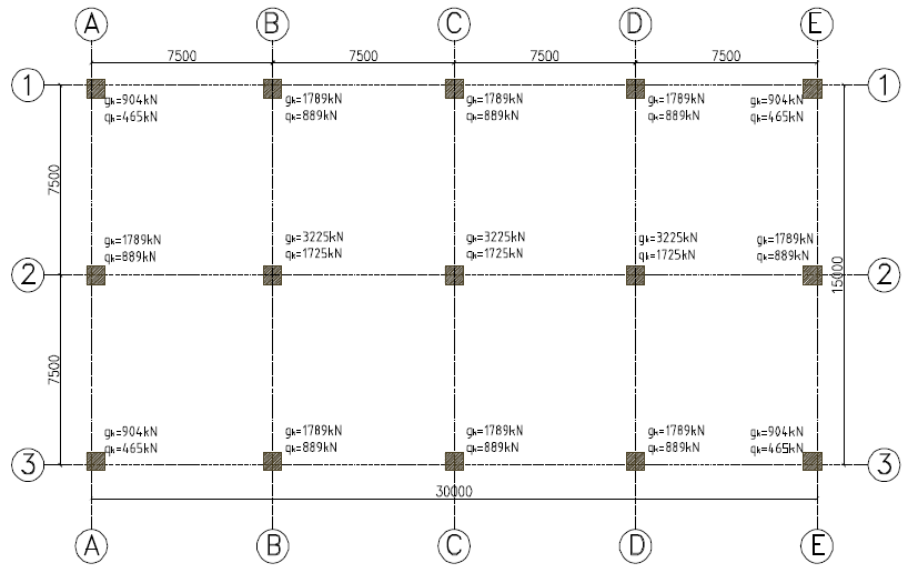
Figure 1 is the column application plan at the base of an 8-story building, showing the loads at serviceability limit state. It is required to find this building on a pile foundation. Using the pile catalogue, carry out sufficient calculation to establish the pile layout and quantity of reinforcing steels required in the pile caps using concrete C25/30 and grade 460 steel.
| Pile diameter (mm) | 400 | 500 | 600 | 750 |
| Safe working load (kN) | 806 | 1343 | 1668 | 2452 |
Column A1 (Typical for A3, E1 & E3)
Pile Layout
Assuming, we want to use two piles for this column, we can determine the pile type required by dividing the loads on the column at serviceability by the number of piles required, which is 2, and then select a suitable pile type from the pile catalogue.
n =\frac { N_{unfactored} }{ 2 }=\frac { 904+465 }{ 2 } \\=684.5kN<806kNWe can adopt, two 400mm diameter piles
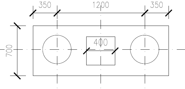
Try an overall depth h=1000mm with an average effective depth of 900mm, the spacing between piles 3 x 400 = 1200mm, and assuming an overhang of 150mm from the piles both ways, length of pile cap =1200+(400/2)+(400/2)+150+150= 1900mm. Width of pile cap = 400 +150 +150 =700mm. The layout of the pile cap is shown as figure 2
Actions @ ULS
{ N }_{ uls }=1.35{ G }_{ k }+{ 1.5Q }_{ k }=1.35(904)+1.5(465)\\ =1917.9kN
w_{sw}=1.35\times1.7\times 0.8\times 1\times 25\\ =45.9kNN=1917.9+45.9\quad =1964kN
Tension Reinforcement
T=\frac { Nl }{ 2d } =\frac { 1964\times \left( 1200/2 \right) }{ 2\times 900 } =655kN{ A }_{ s }=\frac { T }{ 0.87{ f }_{ yk } } =\frac { 655\times { 10 }^{ 3 } }{ 0.87\times 460 } =1637{ mm }^{ 2 }The total area of reinforcement required in both directions As,req = 2 x 1637 =3274mm2
Try 18T16 – 100mm (As,prov =3618mm2)
Verify Minimum Area of Steel
{ A }_{ s,min }=0.26\frac { { f }_{ ctm } }{ { f }_{ yk } } bd\ge 0.0013bd{ f }_{ ctm }=0.3{ f }_{ ck }^{ 2/3 }=0.3\times { 25 }^{ 2/3 }=2.56MPa0.26\times \frac { 2.56 }{ 460 } \times 1900\times 900\ge \\ 0.0013\times 1900\times 900=2474.5{ mm }^{ 2 }<{ A }_{ s,prov }\quad o.kShear Verification
V=\frac { 1951 }{ 2 } =976kN{ a }_{ v }=\frac { 1900 }{ 2 } -\frac { 400 }{ 2 }- \left( 400+150 \right) +\frac { 400 }{ 5 } =280mm { V }_{ Ed }=V\frac { { a }_{ v } }{ 2d } =976\frac { 280 }{ \left( 2\times 900 \right) } =151.8kN{ V }_{ Rd,c }={ 0.12k\left( 100\rho { f }_{ ck } \right) }^{ 1/3 }bd\ge 0.035{ k }^{ 2/3 }{ \sqrt { { f }_{ ck } } }bdk=1+\sqrt { \frac { 200 }{ d } } =1+\sqrt { \frac { 200 }{ 900 } } =1.47<2\rho =\frac { { A }_{ s } }{ bd } =\frac {3618 }{ 1900\times 900 } =0.0021{ V }_{ Rd,c }=0.12\cdot 1.47{ \left( 100\times 0.0021\times 25 \right) }^{ 1/3 }bd\\ \ge 0.035\times { 1.47 }^{ 2/3 }\cdot \sqrt { 25 } bd524.3kN\ > \left( { V }_{ Ed }=151.8kN \right) \quad o.kPunching Verification
Pile spacing has being deliberately chosen at exactly 3 times the pile diameter to avoid further punching checks except at the column face
At the column face:
{ N }_{ Ed }\le { V }_{ Rd,max }{ V }_{ Rd,max }=0.2\left( 1-\frac { { f }_{ ck } }{ 250 } \right) { f }_{ ck }pd0.2\left( 1-\frac { 25 }{ 250 } \right) 25\times \left( 4\times 400 \right) \cdot 900=6480kN\quad >\left( { N }=1951kN \right) \quad o.kColumn B1 (Typical for C1, D1, A2, E2, B3, C3 &D3)
Pile Layout
Assuming three piles for this column, we can determine the pile type required by dividing the loads on the column at serviceability by the number of piles required, which is 3, and then select a suitable pile type from the pile catalogue.
n =\frac { N_{unfactored} }{ 3 }=\frac { 1789+889 }{ 3 } \\=892.66kN<1343kNWe can adopt, three 500mm diameter piles.
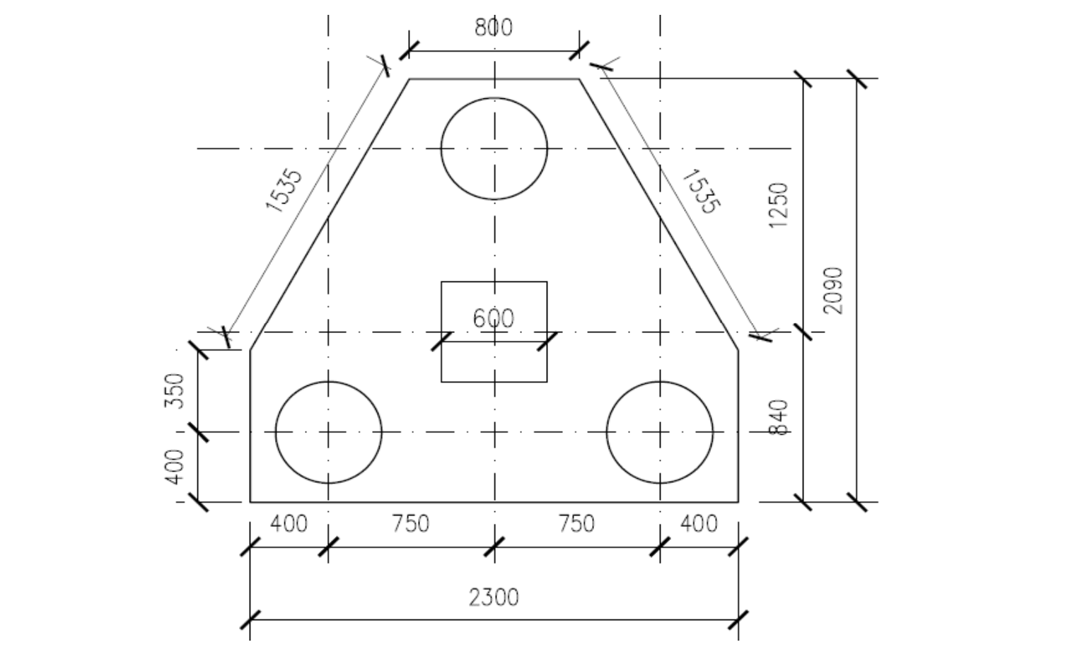
Try an overall depth h=1000mm with an average effective depth of 900mm, the spacing between piles 3 x 500 = 1500mm, and assuming an overhang of 150mm from the piles both ways, length of pile cap =1500+(500/2)+(500/2)+150+150= 2300mm. Width of pile cap = 500 +150 +150 =800mm. The layout of the pile cap is shown as figure 3
Actions @ ULS
{ N }_{ uls }=1.35{ G }_{ k }+{ 1.5Q }_{ k }=1.35(1789)+1.5(889)\\ =3748.7kN
w_{sw}=1.35\times3.86\times 25\\ =130.3kNN=3748.7+130.3\quad =3879kN
Tension Reinforcement
T=\frac { 2Nl }{ 9d } =\frac { 2\times3879\times \left( 1500/2 \right) }{ 9\times 900 } =718.3kN{ A }_{ s }=\frac { T }{ 0.87{ f }_{ yk } } =\frac { 718.3\times { 10 }^{ 3 } }{ 0.87\times 460 } =1795{ mm }^{ 2 }The total area of reinforcement required in both directions As,req = 2 x 1795 =3550mm2
Try 18T16 – 100mm (As,prov =3618mm2)
Verify Minimum Area of Steel
{ A }_{ s,min }=0.26\frac { { f }_{ ctm } }{ { f }_{ yk } } bd\ge 0.0013bd{ f }_{ ctm }=0.3{ f }_{ ck }^{ 2/3 }=0.3\times { 25 }^{ 2/3 }=2.56MPa0.26\times \frac { 2.56 }{ 460 } \times 1900\times 900\ge \\ 0.0013\times 1900\times 900=2474.5{ mm }^{ 2 }<{ A }_{ s,prov }\quad o.kShear Verification
V=\frac { 3879 }{ 3 } =1293kN{ a }_{ v }=\frac { 2300 }{ 2 } -\frac { 600 }{ 2 }- \left( 500+150 \right) +\frac { 500 }{ 5 } =300mm { V }_{ Ed }=V\frac { { a }_{ v } }{ 2d } =1293\frac { 300 }{ \left( 2\times 900 \right) } =215.5kN{ V }_{ Rd,c }={ 0.12k\left( 100\rho { f }_{ ck } \right) }^{ 1/3 }bd\ge 0.035{ k }^{ 2/3 }{ \sqrt { { f }_{ ck } } }bdk=1+\sqrt { \frac { 200 }{ d } } =1+\sqrt { \frac { 200 }{ 900 } } =1.47<2\rho =\frac { { A }_{ s } }{ bd } =\frac {3618 }{ 2300\times 900 } =0.0017{ V }_{ Rd,c }=0.12\cdot 1.47{ \left( 100\times 0.0017\times 25 \right) }^{ 1/3 }bd\\ \ge 0.035\times { 1.47 }^{ 2/3 }\cdot \sqrt { 25 } bd591.5kN\ > \left( { V }_{ Ed }=215.5kN \right) \quad o.kPunching Verification
Pile spacing has being deliberately chosen at exactly 3 times the pile diameter to avoid further punching checks except at the column face
At the column face:
{ N }_{ Ed }\le { V }_{ Rd,max }{ V }_{ Rd,max }=0.2\left( 1-\frac { { f }_{ ck } }{ 250 } \right) { f }_{ ck }pd0.2\left( 1-\frac { 25 }{ 250 } \right) 25\times \left( 4\times 600 \right) \cdot 900=9720kN\quad >\left( { N }=3879kN \right) \quad o.kColumn B2 (Typical for C2 & D2)
Pile Layout
Assuming four piles for this column, we can determine the pile type required by dividing the loads on the column at serviceability by the number of piles required, which is 4, and then select a suitable pile type from the pile catalogue.
n =\frac { N_{unfactored} }{ 4 }=\frac { 3225+1725 }{ 4 } \\=1237.5kN<1343kNWe can adopt, four 500mm diameter piles.
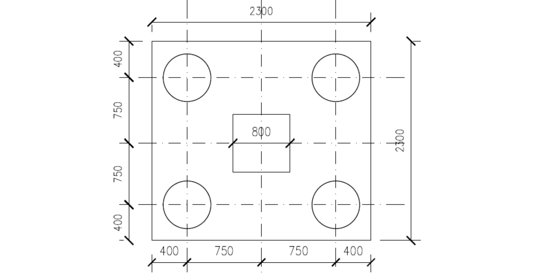
Try an overall depth h=1500mm with an average effective depth of 1400mm, the spacing between piles 3 x 500 = 1500mm, and assuming an overhang of 150mm from the piles both ways, length of pile cap =1500+(500/2)+(500/2)+150+150= 2300mm. Width of pile cap = 1500 + (500/2)+(500/2)+150 +150 =2300mm. The layout of the pile cap is shown as figure 4
Actions @ ULS
{ N }_{ uls }=1.35{ G }_{ k }+{ 1.5Q }_{ k }=1.35(3225)+1.5(1725)\\ =6941.3kN
w_{sw}=1.35\times2.3^2\times 25\times 1.5\\ =321.4kNN=6941.3+321.4=7263kN
Tension Reinforcement
T=\frac { Nl }{ 4d } =\frac { 7263\times \left( 1500/2 \right) }{ 4\times 1400 } =973kN{ A }_{ s }=\frac { T }{ 0.87{ f }_{ yk } } =\frac { 973\times { 10 }^{ 3 } }{ 0.87\times 460 } =2431.3{ mm }^{ 2 }The total area of reinforcement required in both directions As,req = 2 x 2431.3 =4863mm2
Try 18T20 – 125mm (As,prov =5652mm2)
Verify Minimum Area of Steel
{ A }_{ s,min }=0.26\frac { { f }_{ ctm } }{ { f }_{ yk } } bd\ge 0.0013bd{ f }_{ ctm }=0.3{ f }_{ ck }^{ 2/3 }=0.3\times { 25 }^{ 2/3 }=2.56MPa0.26\times \frac { 2.56 }{ 460 } \times 2300\times 1400\ge \\ 0.0013\times 2300\times 140=4659{ mm }^{ 2 }<{ A }_{ s,prov }\quad o.kShear Verification
V=\frac { 7263.5 }{ 2 } =3631.8kN{ a }_{ v }=\frac { 2300 }{ 2 } -\frac { 800 }{ 2 }- \left( 500+150 \right) +\frac { 500 }{ 5 } =200mm { V }_{ Ed }=V\frac { { a }_{ v } }{ 2d } =3631.8\frac { 200 }{ \left( 2\times 1400 \right) } =259.4kN{ V }_{ Rd,c }={ 0.12k\left( 100\rho { f }_{ ck } \right) }^{ 1/3 }bd\ge 0.035{ k }^{ 2/3 }{ \sqrt { { f }_{ ck } } }bdk=1+\sqrt { \frac { 200 }{ d } } =1+\sqrt { \frac { 200 }{ 1400 } } =1.38<2\rho =\frac { { A }_{ s } }{ bd } =\frac {5652 }{ 2300\times 1400 } =0.0018{ V }_{ Rd,c }=0.12\cdot 1.38{ \left( 100\times 0.0018\times 25 \right) }^{ 1/3 }bd\\ \ge 0.035\times { 1.38 }^{ 2/3 }\cdot \sqrt { 25 } bd880.3kN\ > \left( { V }_{ Ed }=259.4kN \right) \quad o.kPunching Verification
Pile spacing has being deliberately chosen at exactly 3 times the pile diameter to avoid further punching checks except at the column face.
At the column face:
{ N }_{ Ed }\le { V }_{ Rd,max }{ V }_{ Rd,max }=0.2\left( 1-\frac { { f }_{ ck } }{ 250 } \right) { f }_{ ck }pd0.2\left( 1-\frac { 25 }{ 250 } \right) 25\times \left( 4\times 800 \right) \cdot 1400=20160kN\quad >\left( { N }=7263kN \right) \quad o.kHaving provided the longitudinal reinforcement required in the pile caps, an additional layer of steel is usually provided on the surface of the pile cap, often known as the “anti-burst steel“. This is provided based on the minimum area of steel. The pile themselves are designed as axially loaded “stocky “columns, which in many instances would only require minimum area of steel.
Design Resume
Pile- Cap (Type 1)
⦁ Main Bars: 18T16mm @100 c/c Bars
⦁ Distribution Bars: T16mm Bars @ 100 c/c
⦁ Anti-Bust Steel: T12mm Bars @200 c/c
Pile- Cap (Type 2)
⦁ Main Bars: 18T16mm @100 c/c Bars
⦁ Distribution Bars: T16mm Bars @ 100 c/c
⦁ Anti-Bust Steel: T12mm Bars @200 c/c
Pile- Cap (Type 3)
⦁ Main Bars: 18T20mm @125 c/c Bars
⦁ Distribution Bars: T16mm Bars @ 100 c/c
⦁ Anti-Bust Steel: T12mm Bars @200 c/
Thank You!