Estimating deflection in trusses is considered a challenging subject as it often requires tedious calculations when done by hand. This article presents a straightforward method for determining deflection in trusses.
Estimating deflections in trusses has long been considered a problematic subject for structural engineers. This is because in contrast to simple plane member like beams and frames, trusses are made up of interconnected elements. Each of these elements have a contribution to make to the overall deflection of truss.
The earliest introduction and still the most popular method of estimating deflection in trusses in the absence of FEA or computer programs is the ‘unit load method.’ The unit load method is based on the principle of virtual work. It requires that a fictitious load be applied at the joint in the truss where the displacement is been sought, the resulting internal forces are then determined and used to compute the deflection. (See: Displacement of Trusses Principle of Virtual Work).
Supposing we intend to determine the displacement of a joint in a truss, the virtual work equation for the truss can be expressed as:
1.\Delta =\sum \frac{nNL}{EA}Where:
- 1= external virtual unit load acting on the truss joint in the stated direction of Δ
- n = internal virtual normal force in a truss member caused by the external virtual unit load
- Δ = external joint displacement caused by the real loads on the truss
- N = internal normal force in a truss member caused by the real loads
- L = length of a member
- A = cross-sectional area of a member
- E = modulus of elasticity of a member.
Engineers who use the unit load method can attest to the time-consuming nature of this approach in the computation of deflections. Why? Because two types of member stresses (real & fictitious) must always be computed before deflection can be evaluated.
This article presents a simplified approach that precludes the evaluation of member stresses, so that deflection of trusses can readily be estimated by hand calculations.
Principle of Truss Deflection
In order to simplify the estimation of vertical deflection in trusses, trusses can be idealized as an equivalent beam, so that deflection is then calculated as though the truss is a beam, using standard formulae. In utilizing this approach, however, there is a distinction that must be recognized between a typical beam and the equivalent beam of a truss. Deflection in planar members is always composed of two components: flexural and shear. In a typical beam, the shear component insignificant, hence it has been the practice to omit it in computing deflections in normal beams. The same is not true for trusses, trusses are made up of web members which are significantly susceptible to shear deformation. Thus, to arrive at a more accurate value of deflection in trusses, using this method, the shear component must always be considered.
The flexural component is readily computed using the well-established deflection equations as in any standard structural analysis references. The only difference being that the second moment area I in the deflection equations are determined by applying the parallel axis theorem to the chord members. On the other hand, since the shear component are rarely required, there are mostly no well-established equations in structural analysis referenced texts. Thus, the crux of this article is a concept of estimating shear deflections.
W Tsai (1975) presented equations for estimating shear deformation in trusses by simplifying trusses into four basic types, namely N-braced (Pratt type), W-Braced (Warren type), K-braced type and X-braced type. This article only focus on the N and W-braced type as this are the most popular truss forms. However, the reader can consider the referenced text which is listed in the ‘sources & citation’ section of this article for the other truss forms.
N-Braced Type
Figure 1 illustrates the shear deformation in a typical N-braced (Pratt) truss. This deformation consists of two portions: one due to vertical members and the other due to diagonal members. Assuming a shear force, V exists in the panel, the elongation in the diagonal AD produces a vertical displacement DD’ equal to:
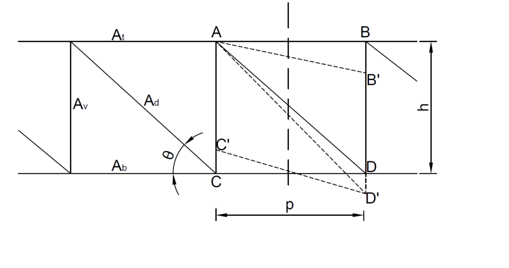
\frac{V\times p}{EA_{d}}sin^2\theta cos\thetaWhile the displacement of the vertical AC is given as:
\frac{Vh}{EA_{v}}Thus, we can compute the deflection difference between two joints at a distance Ls apart by prorating Ls to the panel length p as:
\Delta_s =\frac{VL_s}{EA_d}{( {\frac{1}{sin^2\theta cos\theta}+\frac{A_d}{A_p}tan\theta})}For practical applications the shear force V may not be constant throughout the truss plan. When this is the case, V represents an average value of the shear force over the distance Ls
Worked Example – N Truss
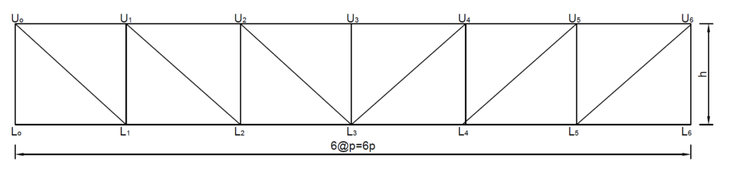
Figure 2 is a 6 panel simply supported N braced truss. The depth of the truss is equal to the panel length. The cross-sectional area of each chord member is 2A and of each web member is A. Determine the deflection at midspan, for two load conditions:
- A load W applied at the midspan (joint L3)
- A set of loads W applied at each joint.
To determine the deflection in this truss, the truss equivalent beam is treated as a simply supported beam. The beam is subjected to two types of loads. The first loading condition is a concentrated load at midspan while the second load condition can be treated as a uniformly distributed load (W/p) over the whole span.
The moment of inertia can be estimated by the parallel axis theorem or by averaging the cross-sectional area of the chord members about their neutral axis in the depth.
The moment of Inertia is given as:
I_{truss}=\frac{A_tA_b}{A_t+A_b}h^2where: At & Ab are the cross-sectional area of the upper and lower chords respectively, and h is the depth of the truss. And At = Ab = 2A, and h = p
I =\frac{(2A)^2}{2A+2A}\times p^2 ={Ap^2}The distance for bending deflection is given as L = 6p, while the distance for shear deflections is given as Ls = 3p. The area of web members is Ad = Av = A
For Concentrated Load
Bending Deflection:
\Delta_b =\frac{WL^3}{48EI} =\frac{W\times(6p)^3}{48E\times Ap^2}=\frac{4.5Wp}{EA}Shear Deflection:
\Delta_s=\frac{VL_s}{EA_d}{( {\frac{1}{sin^2\theta cos\theta}+\frac{A_d}{A_p}tan\theta})}V=0.5W
\Delta_s=\frac{0.5W\times3p}{EA}\times( \frac{1}{0.353}+1) =\frac{5.75Wp}{EA}Therefore, the approximate total deflection at midspan is given as:
\Delta=\Delta_b+\Delta_s =\frac{10.25Wp}{EA}For Uniformly Distributed Load
Bending Deflection:
\Delta_b =\frac{5wL^3}{384EI} =\frac{(W/p\times(6p)^4}{384E\times Ap^2}=\frac{101.25Wp}{EA}Shear Deflection:
\Delta_s=\frac{VL_s}{EA_d}{( {\frac{1}{sin^2\theta cos\theta}+\frac{A_d}{A_p}tan\theta})}V is averaged over a distance of Ls = 3p
V=2W
\Delta_s=\frac{2W\times3p}{EA}\times( \frac{1}{0.353}+1) =\frac{23Wp}{EA}Therefore, the approximate total deflection at midspan is given as:
\Delta=\Delta_b+\Delta_s =\frac{124.25Wp}{EA}W-Braced Type
Figure 4 illustrates a portion of a Warren truss shear deformation. The stress distribution in a warren truss is similar to those of an N-truss. However, because the form is different, the shear deformation is slightly different. From figure 4, the displacement DD’ due to diagonals is the same as that of the N-type. However, the displacement of the vertical is different. Also, since verticals within Ls do not affect the deflection difference between ends of Ls, only the posts at both ends of Ls contributes to their elongation to the shear deflection.
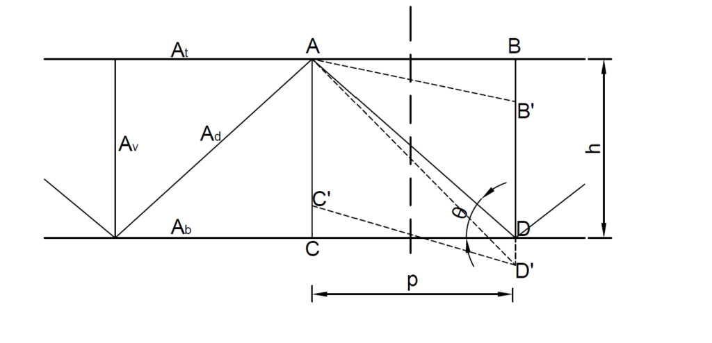
The total shear deflection can thus be written as:
\Delta_s=\frac{VL_s}{EA_d}{( {\frac{1}{sin^2\theta cos\theta}+c\frac{h}{L_s}\frac{A_d}{A_p}})}Where c is a constant which is 0,1 or 2, depending on whether no vertical, one vertical, or two verticals are at both sides of Ls are under stress.
Practical Example
Figure 2 shows a simply supported 24m transition truss required to support the loads from floor beams and a steel column at midspan. Assume the design load from the floor beams on each joint is 175kN and the load from the steel column is 2000kN. Verify that the overall deflection of the truss is within L/500. (Note: Area of chord members is approximately equal to two times the area of the web members).
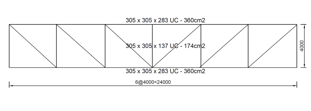
There are two load cases that needs to be considered here. The load from the floor beams applied at the nodes can be considered to be a UDL. While the load from the steel column can be assumed to be a point load applied at midspan. Therefore:
Deflection due to Point load:
\Delta_1=\frac{10.25Wp}{EA} =\frac{10.25\times2000\times10^3\times 4000}{210000\times174\times10^2}=22.44mm
Deflection due to UDL:
\Delta_1=\frac{124.25Wp}{EA} =\frac{124.25\times175\times10^3\times 4000}{210000\times174\times10^2}=23.80mm
Total Deflection:
\Delta=\Delta_1+\Delta_2=22.44+23.80=46.24mm
Limiting Value of Deflection:
\frac{L}{500} =\frac{24000}{500}= 48mmSince the actual deflection is less than the limiting value, the truss satisfies the deflection verification.
Sources & Citation
- W. Tsai (1977) “A simplified Approach to Truss Deflections.” American Institute of Steel Construction (AISC). 13(3)