Introduction
The concept of pile foundation is incomplete without discussing pile caps because the loads from the superstructure of a structure cannot be transferred directly on piles as it is most unlikely that a vertical within the superstructure will require a single pile to support the applied loads. It is common, however, to use piles in group, hence in order to distribute the load on the pile group, a pile cap is usually provided on the pile group, thereby efficiently transmitting the loads from the superstructure into the piles.
This article concerns the design of pile caps for a small group of piles, between 2-4 piles and purely axially loaded. It doesn’t consider large pile group and pile caps subjected to horizontal loads and/or moments due to the complexity in obtaining the load distribution of the pile group and the influence of differential settlement which further complicates their design. However, guidance on this aspect of pile caps can be obtained from the reference and further reading section of the article.
Pile Cap Design
The layout of the pile group is largely determined from the magnitude and location of actions they are to support from the superstructure. They are grouped together based on the pile’s capacity to support axial forces that can be either tension or compression, depending on the direction of the axial forces induced into the pile-cap from actions generated by the superstructure.
For simplicity, the location of piles with reference to the point of axial force application should be symmetrical. The proximity of piles to one another should be at least 3 × diameter of the pile. For pile-caps with 1 or 2 piles, some restraint needs to be provided orthogonally to the pile(s), which is usually achieved via ground beams. Figure 1 provides guidance on the location of piles in 2, 3 and 4 pile pile-caps where s is the spacing between piles.

Determining axial forces in piles within pile-caps
When a pile cap is supporting an axial force N that is placed within the centroid of the pile group, the axial force in each pile is defined as:
\frac { N }{ n } Where: n is the number of piles.
This only applies to piles within a
Design of Tension Reinforcement
Two methods of design are common: the beam theory and the strut &tie approach. In the former case the pile cap is treated as an inverted beam and is designed for the usual conditions of flexure and shear. The strut-tie assumes the reinforcement within the pile-cap is acting as if it were part of a truss, with the compression stresses being withstood by the concrete and the tension by the steel reinforcement. This method is applicable for pile-caps with less than 6 piles and is in fact the approach being considered for pile cap design in this article.
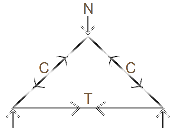
Figure 2 shows the forces that pass through a pile-cap into the piles and how the strut and tie method is applied to it. It indicates how the depth of the pile-cap determines the magnitude of the forces within the concrete and the tension reinforcement. Typically the angle of the truss is set at 45º, which is then used to determine the depth of the pile-cap. Further iterations of this angle may be necessary as the size of the pile-cap is altered and/or the element it is supporting is modified to overcome geometry constraints and other extraneous design criteria. This can result in having a shallower angle that increases the tension in the reinforcement – as does the compression stress in the struts within the pile-cap.
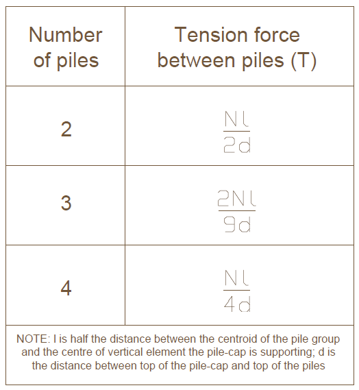
When the location of the axial force is not eccentric, the applied tension force between each pile can be calculated using table in figure 3
The tension reinforcement As required in the pile-cap is then defined as
{ A }_{ S }=\frac { T }{ 0.87{ f }_{ yk } }Where: fyk is the tension strength of the reinforcement, which is typically within the range of 400 – 500 N/mm2.
Design of Shear Reinforcement
A critical shear plane adjacent to the vertical element that the pile-cap is supporting needs to be checked to determine whether or not it fails in shear. The plane’s location is based on the distance av, which is the dimension from the face of the vertical element the pile-cap is supporting and the face of a pile plus 0.2 × the pile diameter. This plane’s location is further explained in Figure 4. The shear verification is then carried out the same way we did for concrete beams.

An additional check with respect to shear is required at the face of the vertical element the pile-cap supports.
{ N }_{ ED }<{ V }_{ RD,max }Ned is the design axial load on the pile cap while VRd,max is the maximum shear resistance defined as
{ V }_{ RD,max }=0.2\left[ 1-\frac { { f }_{ ck } }{ 250 } \right] { f }_{ ck }pd- p is the perimeter length of the vertical element of the superstructure
- d is the depth of the pile-cap
Pile Caps Reinforcement Detailing
There are several unique detailing requirements that are specific to pile caps. The anchorage length of the tension reinforcement is dependent on the bond conditions between the concrete and the steel. In the case of pile-caps, a good condition bond requires the reinforcement to be located within the 250mm depth of the concrete pour. For anything placed outside of that zone, the bond is considered to be ‘poor’. For more information on this see Clause 8.4.2 in BS EN 1992-1-1. The table provided in figure 5 shows the anchorage lengths for reinforcement bars based on concrete strength and bond conditions. A more accurate tension reinforcement anchorage length can be calculated using the guidance provided in Clause 8.4.3 of EN 19921-1. The minimum diameter of reinforcement used in a pile-cap is 8mm

Also, the minimum area of steel as defined for slabs & beams should also be verified to ensure that it is not critical
Worked Example
A 600×600 concrete column carries an axial design action of 4250 kN. Design a 4 pile pile-cap to support the column. The piles are 500mm in diameter cylindrical concrete. Design the pile cap completely using C30/37 concrete with 500mpa high tensile steel assuming the column to be placed in the centroid of the pile group.
Geometry of the pile-cap
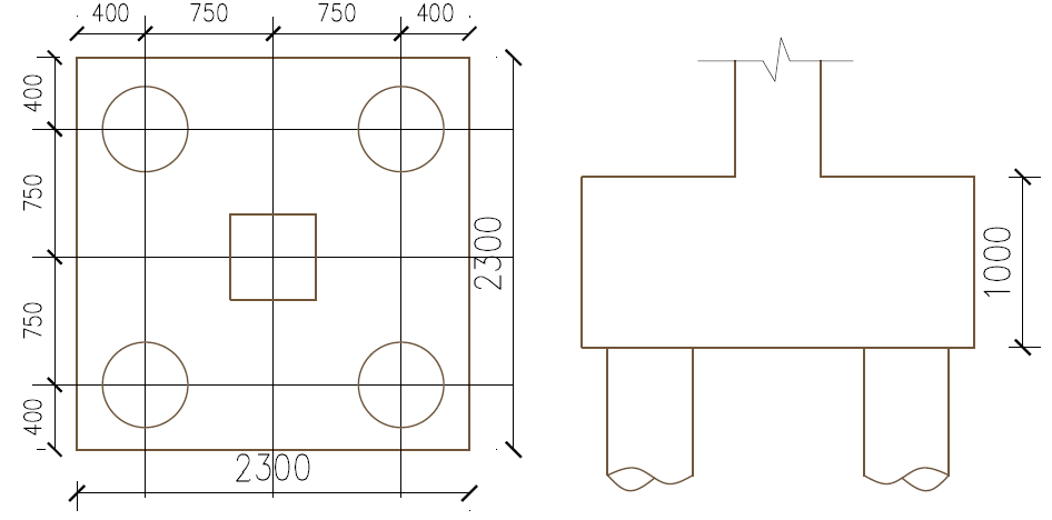
Try an overall depth h=1000mm with an average effective depth of 900mm, the spacing between piles = 3×500=1500mm and assuming an overhang of 400mm both ways. width of pile cap = 400+1500+400 = 2300mm. Figure 4 shows the trial geometry of the pile cap.
Tension Reinforcement
from figure 3
T=\frac { Nl }{ 4d } =\frac { 4250\times (1500/2)\cdot { 10 }^{ 3 } }{ 4\times 900 } =885.42kN{ A }_{ s }=\frac { T }{ 0.87{ f }_{ yk } } =\frac { 885.42\times { 10 }^{ 3 } }{ 0.87\times 500 } =2035.45{ mm }^{ 2 }The area of reinforcement required in both direction is given as:
{ A }_{ s,req }=2\times 2035.45=4070.9{ mm }^{ 2 }\\ Try\quad 23H16 @100c/c\quad ({ A }_{ s,prov }=4623{ mm }^{ 2 })\\ Verify Minimum Area of Steel
{ A }_{ smin }=0.26\frac { { f }_{ ctm } }{ { f }_{ yk } } bd\quad \ge \quad 0.0013bd\\ { f }_{ ctm }=0.3\times { 30 }^{ 2/3 }\quad =2.9mpa\\ \qquad =0.26\cdot \frac { 2.9 }{ 500 } \times 2300\times 900\ge \\ \qquad =0.0013\times 2300\times 900\\ \qquad =3125.6{ mm }^{ 2 }<{ A }_{ s,pro }\\ Shear Verification
V=\frac { 4250 }{ 2 } =2125kN{ a }_{ v }=\frac { 2300 }{ 2 } -400-\frac { 600 }{ 2 } +\frac { 500 }{ 5 } =550mm\\ { V }_{ ED }=2125\frac { { a }_{ v } }{ 2d } =2125\frac { 550 }{ 2\times 900 } =649.31kN\\ { V }_{ RD,c }=0.12k(100\rho { f }_{ ck })^{ 1/3 }bd\ge 0.035{ k }^{ 3/2 }\sqrt { { f }_{ ck } } bd\\ k=1+\sqrt { \frac { 200 }{ d } } =1+\sqrt { \frac { 200 }{ 900 } } =1.47<2\\ \rho =\frac { { A }_{ s } }{ bd } =\frac { 4623 }{ 2300\times 900 } =2.23\times { 10 }^{ -3 }\\{ V }_{ RD,c }=0.12\cdot 1.47(100\times 0.0023\times 30)^{ 1/3 }\times bd\ge \\ =0.035\times 1.47^{ 2/3 }\cdot \sqrt { 30 }\times bd\\ \qquad \quad =673.2kN(\ge { V }_{ ED }=649.31kN)Punching Verification
Since pile spacing as been taking at exactly 3times the pile diameter, no punching verification is necessary, except at the column face.
{ N }_{ ED }<{ V }_{ RD,max }{ V }_{ RD,max }=0.2\left( 1-\frac { { f }_{ ck } }{ 250 } \right) { f }_{ ck }pd\\ 0.2\left( 1-\frac { 30 }{ 250 } \right) 30\times (4\times 600)\cdot 900\\ =11,404.8kN\quad (>{ N }_{ ED }=4250kN)Further Reading & References
- Mosley W. H., Hulse R. and Bungay J.H. (2012) Reinforced Concrete Design to Eurocode 2 (7th ed.) Basingstoke, UK: Palgrave MacMillan
- Tomlinson M. and Woodward J. (2007) Pile Design and Construction Practice (5th ed.) Boca Raton, Florida: CRC Press
- Webster R. and Brooker O. (2007) How to design concrete structures using Eurocode 2 – Part 6. Foundations [Online] Available at: www.concretecentre.com/pdf/ publicationlibrary/how2_foundations.pdf (Accessed: November 2013)
- The Institution of Structural Engineers (2013). Designing a Pile Cap. Technical guidance notes (level 2).
Thank You!
canadianpharmacymeds com – but cialis online generic tadalafil from india
viagra online 100mg – viagra 20 mg online viagra citrate 120mg
buy tadalafil online no prescription – generic cialis buy uk cheap cialis for sale
ivermectin buy uk – ivermecti ivermectin buy
rivers casino – real casino online online casino usa real money
medicine for impotence – ed pills online ed medications
prednisone uk – prednisonepll buy prednisone from india
good pill pharmacy – Cialis mail order usa how to get generic cialis
ivermectin 1 topical cream – stromectole online ivermectin price canada
Дом Гуччи смотреть онлайн
non prescription ed pills – signs of ed erectile dysfunction remedies
ventolin over the counter – cost of ventolin in usa ipratropium albuterol
cytotec generic – canadian pharmacy cytotec cytotec cost in south africa
doxycycline – where to buy doxycycline over the counter doxycycline 100mg cap tab
32 neurontin – synthroid for sale usa synthroid average cost
Keflex Instruction
order viagra from canada – female viagra real cialis generic levitra viagra
Siemens Levitra 20mg
40 mg cialis online – cialis price canada
https://buypropeciaon.com/ – Propecia
http://buystromectolon.com/ – ivermectin cats
vardenafil coupon – buy cialis and vardenafil onlinevardenafil coupon vardenafil purchase
Cialis
https://buytadalafshop.com/ – Cialis
stromectol 3 mg dosage – price of ivermectin liquid ivermectin medication
Online Pharmacy In Canada
3000mg prednisone – can i buy 10mg prednisone over the counter prednisone tablets
where to purchase accutane – isotretinoin 20mg accutane online usa
фильмы онлайн бесплатно
buy amoxicilin 500 mg – amoxicilina 500 mg from mexico buy amoxil
Propecia
cialis depression
medrol 5mg tablets – site medication lyrica 50 mg
sildenafil cost usa – Overnight canadian viagra sildenafil soft tabs generic
Viagra
canada rx cialis – Cialis online ordering best price for cialis
ivermectin 400 mg brands – ivermectin medication ivermectin 5 mg
prednisone buy online – canada prednisone 50 mg prednisone over the counter canada
I am continually searching online for articles that can benefit me. Thanks!