A Stringer beam is a structural member that
Stringer beams when utilized in staircase construction can be designed either with two edge beams (simply supported) or with a central beam (double cantilever) See Figure 1.
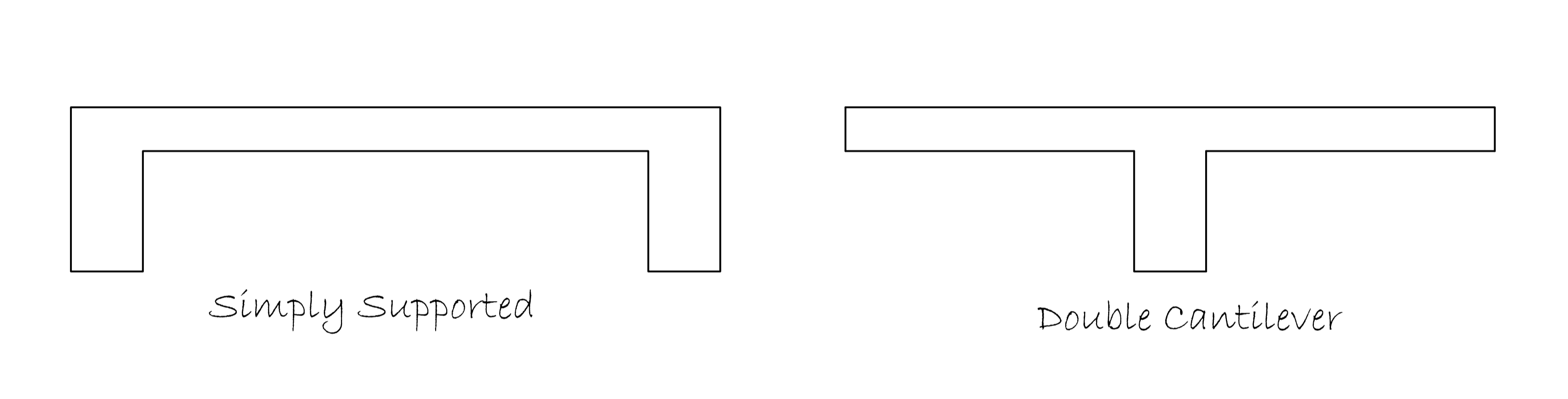
Figure 1: Types of stringer beam
In the design of staircases with two edge beams, the staircase section is idealized as simply supported between the two edge beams. Therefore, the beams are designed as Inverted L beams while the stair itself as simply supported slab. For the double cantilever, the staircase section is idealized as a T- section therefore the stringer beam is designed as a flanged T beam and the waste of the staircase as spanning transversely (like a cantilever). In each case a primary beam/support will be required to support the stringer beam. These supports are normally designed as carrying point loads from the stringer beam in addition to any other load they may be carrying.
Worked Example
Figure 2.0 shows the plan of the second flight of a staircase spanning 7.0m between supports. Assuming we design a staircase spanning transversely and supported by beams at the supports, this would result in an uneconomical staircase section due to the thickness of the waste that would ensue and quantity of steel that will be required to control deflection. A Stringer beam is therefore provided in order to make take care of the foregoing reasons. In this case a central stringer beam (double cantilever) type is designed using the design data in Table 1.
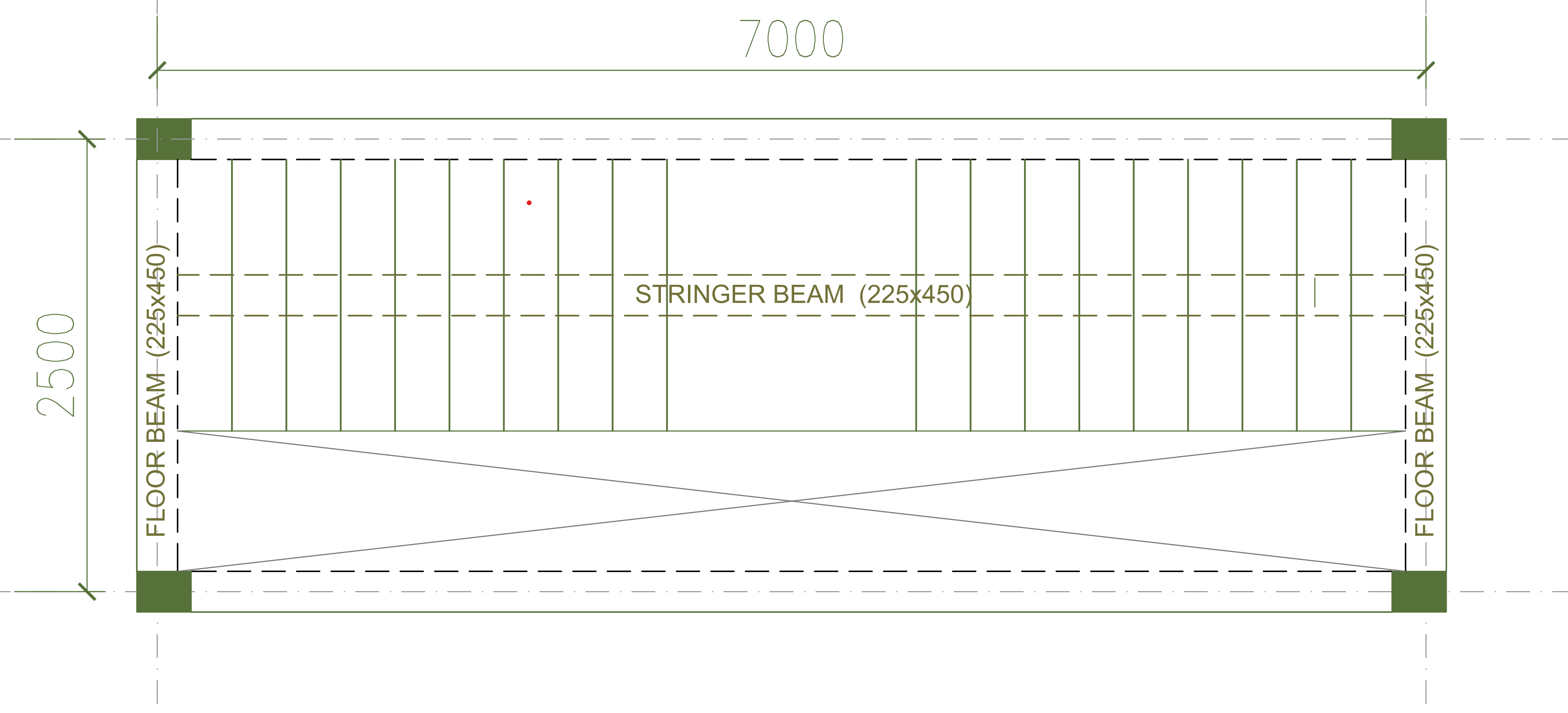
Figure 2: Worked example-stair plan
| Concrete | C20/25 |
| Reinforcement | 410Mpa |
| Stair width | 1500mm |
| Risers | 150mm |
| Threads | 300mm |
| Imposed Loading (Mall) | 4kN/m2 |
Actions
Permanent Actions
Permanent action includes the weight of the stair waste, weight of steps, load from finishes and balustrades. Because the waste of the stair is inclined, the permanent actions due to the slab waste, finishes and any other applied loads except the step must be corrected by a slope factor.
a.\quad 150mm\quad concrete\quad waste\quad \\ \quad =0.15\times 25\quad =3.75kN/{ m }^{ 2} b.\quad finishes =1.5kN/{ m }^{ 2 }c.\quad balustrade =0.5kN/{ m }^{ 2 }d.\quad steps=\frac { 0.15 }{ 2 } \times 25=1.88kN/{ m }^{ 2 }g_{k}=(3.75+1.5+0.5)\times1.22+1.88 \\ =8.32kN/m^{2}Variable Actions
b.\quad Imposed\quad load =4kN/{ m }^{ 2 }q_{k} =4kN/m^{2}Design Value of Actions
Using Eqn 6.10 of BS EN 1990:
n_{s}=\quad 1.35{ g }_{ k }+{ 1.5q }_{ k }=(1.35\times8.32)+(1.5\times4)\\ \qquad \qquad \qquad = 17.2kN/{ m }^{ 2 }Actions on Stringer Beam
a.\quad stair =17.2\times1.5=26.6kN/m^{2}b.\quad beam=(0.225\times0.3)\times 25\times1.35 =2.3kN/m^{2}w=26.6+2.3=28.9kN/m^{2}Structural Analysis
Since the beam is simply supported, the equation for obtaining the bending moment and shear force is pretty straightforward.
Bending Moment
M_{Ed}=\frac { w l^{2} }{ 8 } = \frac { 28.9 \times7^{2} }{ 8 }=177kN.mShear Force
V_{Ed}=\frac { w l }{ 2 } = \frac { 28.9 \times7 }{ 2}=101.2kNFlexural Design
M_{Ed}=177kN.mAssuming cover to reinforcement of 30mm, 20mm tensile bars in two layers, 16mm compression bars & 8mm links
{ d }^{ ' }=\left( { c }_{ nom }+links+\phi /2 \right) \\=50+10+16/2=68mm{ d }=h-\left( { c }_{ nom }+links+\phi /2+\phi \right)\\=450-\left( 25+8+20/2+20 \right) =387mm b={ b }_{ eff }=1500mm k=\frac { { M }_{ Ed } }{ b{ d }^{ 2 }{ f }_{ ck } } =\frac { 177\times { 10 }^{ 6 } }{ 1500\times { 387 }^{ 2 }\times 20 } =0.039z=0.95d=0.95\times387=367.7mm
{ A }_{ s,req }=\frac { { M }_{ Ed } }{ 0.87{ f }_{ yk }z } =\frac { 177\times { 10 }^{ 6 } }{ 0.87\times 410\times 367.7 } \\=1349.5{ mm }^{ 2 }Use 5Y20mm bars Bottom. (Two layers) (As, prov = 1570mm2)
Shear Design
{ V }_{ Ed }=\quad 101.2kNBy inspection, the maximum shear force is less than max. shear resistance of the concrete section, therefore the section is adequate however, nominal shear reinforcement must be provided:
\theta =0.5{ sin }^{ -1 }\left( \frac { { 5.56V }_{ Ed } }{ { b }_{ w }d\left( 1-{ f }_{ ck }/250 \right) { f }_{ ck } } \right)=0.5{ sin }^{ -1 }\left( \frac { 5.56\times 101.2\times { 10 }^{ 3 } }{ 225\times 387\left( 1-20/250 \right) 20 } \right) \\=10.3cot\theta =5.5>\quad 2.5\quad ;\quad take\quad cot\theta =2.5
Therefore, the area of shear reinforcement required:
\frac { { A }_{ sv } }{ { s }_{ v } } \ge \frac { { V }_{ Ed } }{ zcot\theta { f }_{ wd } }=\frac { 101.2\times { 10 }^{ 3 } }{ \left( 0.9\times 387\times 2.5 \right) \times 0.87\times410 } =0.33max\quad spacing\quad =0.75d=290.25mm
Use Y8mm – 200mm centers (0.51)
Deflection Verification
Deflection of the Stringer beam is carried out by censuring that the actual span – depth ratio is less than the limiting value. In this case, this beam has been sized conservatively based on the preliminary sizing rules, hence the check shouldn’t be critical.
Limiting Span-Depth Ratio
{ \left[ \frac { l }{ d } \right] }_{ limit }=N\cdot K\cdot F1\cdot F2\cdot F3\rho =\frac { { A }_{ s,req } }{ { A }_{ c } } =\frac { 1349.5 }{ \left( 1500\times 387 \right) } =0.0023 { \rho }_{ o }={ 10 }^{ -3 }\sqrt { { f }_{ ck } } ={ 10 }^{ -3 }\sqrt { 30 } =0.0055N=11+\frac { 1.5\sqrt { { f }_{ ck } } { \rho }_{ o } }{ \rho } +3.2\sqrt { { f }_{ ck } } { \left( \frac { { \rho }_{ o } }{ \rho } \right) }^{ 3/2 } \\ =79.9\frac { { b }_{ eff } }{ b } =\frac { 1500 }{ 225 } =6.7>3\quad ;\quad F1\quad =0.8 F2\quad =\frac { 7 }{ { l }_{ eff } } =\frac { 7 }{ 7 } =1\quad \\ K=1.3\quad (end\quad spans)F3=\frac { 310 }{ { \sigma }_{ s } } \le 1.5 { \sigma }_{ s }=\frac { { f }_{ yk } }{ { \gamma }_{ s } } \left[ \frac { { g }_{ k }+{ \varphi }_{ 2 }{ q }_{ k } }{ { w }_{ d } } \right] \left( \frac { { A }_{ s,req } }{ { A }_{ s,pro } } \right)=\frac { 460 }{ 1.15 } \left[ \frac { 8.32+0.6(4) }{ 17.2 } \right] \frac { 1349.5 }{ 1570 } \\=214.3Mpa F3=\frac { 310 }{ 214.3 } =1.45\le 1.5 \left[ \frac { l }{ d } \right] _{ limit }=79.9\times 1.3\times 0.8\times 1\times 1.45\\ =120.5Actual Span – Depth Ratio
{ \left[ \frac { l }{ d } \right] }_{ Actual }=\frac { span }{ effective\quad depth }= \frac { 7000 }{ 387 } =18.09The limiting span-effective depth ratio is greater than actual; thus, deflection is deemed satisfactory.
See: Preliminary Sizing of Structural Elements
Stair Waste
The stair waste itself require steel bars at the top in-order to accommodate the imposed tensile stresses on the cantilever. This can be designed for the stair design load, as a cantilever slab, however, for most staircases nominal reinforcement steel based on minimum area of steel should be sufficient to satisfy this requirement.
Use Y10mm – 200mm centers both ways (Top) (393mm2/m)
figure 3 shown below, shows the typical section through the stair flight.

Figure 3: Typical section through stair flight
where can i buy cialis – free cialis where to get cialis online
viagra gel tabs – best place buy viagra online can you buy viagra in australia
cialis medication cost – tadalafil 20 mg price canada order cialis without a prescription
ivermectin 3mg dosage – ivermectin 500ml ivermectin new zealand
casino moons online casino – wind creek casino online play slots online
cheap erectile dysfunction pill – erectile dysfunction pills generic ed drugs
tadalafil canada generic over the counter – Cialis generic online pharmacy in turkey
stromectol buy uk – ivermectin cost in usa ivermectin uk buy
what are ed drugs – pharmacy drugs best ed medication
ventolin australia price – gnrventolin albuterol sulfate
buy cytotec online with paypal – cytotec 100 mg cytotec 100 mg cost
buy doxycycline online canada – can you buy doxycycline over the counter in nz doxycycline uk online
buy neurontin canadian pharmacy – neurontin 300mg levothyroxine 125 mcg tab
viagra pills pharmacy – where can you buy female viagra generic viagra online
cialis for sale without pre kiminvog viagra pills without prescription – buy online tadalafil cialis 50
vardenafil generic name – order vardenafil canada cheap vardenafil online uk
ivermectin over counter – stromectol 0.5 mg
prednisone without prescription medication – prednisone over the counter australia prednisolone vs prednisone
accutane 5 mg online – buy accutane cream order cheap accutane
amoxicillin drug – buy amoxicilina noscript buy amoxicilina noscript canada
ivermectin 250ml
medrol tablets 16mg – lyrica 600 mg lyrica 75 price
prescription drugs cheap generic drugs from india – soma therapy ed
furosemide 40 mg tablet order lasix HaitO Acake
sildenafil pills in india – Buy viagra us cheap brand viagra
furosemide cost cvs furosemide pill HaitO Acake
furosemide over the counter furosemide 40 mg tablet HaitO Acake
cialis cost comparison – Brand name cialis 20 mg tadalafil best price
lasix no prescription over the counter lasix at walmart HaitO Acake
stromectol 0.5 mg – stromectol ivermectin tablets ivermectin 12mg online
order prednisone 10mg – steroids prednisone for sale no prescription online prednisone