Introduction
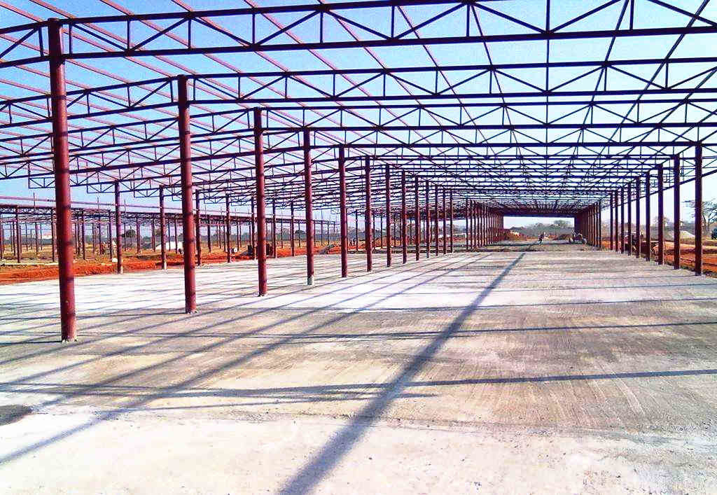
Many problems of long spanning in structural engineering can be resolved through the use of a steel truss. These days, long span structures are very popular– from sport arena roofs to auditorium galleries, airport terminals, railway stations etc. Trusses are arguably the most structurally efficient and cost-effective solution available. Compared with the I and H sections as alternatives, they are very light weighted and basically stiffer which means that their deflection is invariably less under any given load arrangement. Also, where a system of concentrated actions is to be sustained over a large span, such as in transfer structures found in multi-storey buildings, they are highly effective.
In a previous article titled- “Structural Aspects of Selecting Plane Steel Trusses” the concept of steel trusses was laid. The article focused on the alternative forms of planar steel trusses available. The article also justified where the alternative forms of steel trusses might be appropriate with emphasis on the design considerations. It is important to state here, that the list of structural forms provided in that article is not exhaustive, there are several other forms available, however, these are only an extension of those listed. In this article, the design of steel trusses will be explained in details.
Preliminary Aspect of Design
The first step in the process of designing a steel truss is to select this structural form. This depends on several factors. For the structural engineer, safety, buildability, economy and structural behaviour under loads are the most important. In-fact structural behaviour under loads is arguably the most determining factor. Rightly so, safety and economy will depend on the truss behaviour under the system of applied loads. With respect to behaviour, the basic principle in selecting a truss form is to restrict the longer steel elements in tension while the shorter elements in compression. This requires a critical examination of all design load-cases and load combinations. The most onerous load combination should always dictate the structural form to use.
Having selected the truss form which must’ve being in additional to the structural engineer’s considerations selected on the basis of the architectural requirement. The next step would be to immediately consider aspects of serviceability. The overall depth of a truss must be chosen to satisfy the serviceability limit state of deflection. This is easily satisfied by pre-sizing the truss using a span: depth value of between 10-15.
In addition to the above points, a good truss form, for efficiency must allow the following extra consideration.
- The inclination of the diagonal members in the truss relative to the chords should be within the range of 35° – 55°.
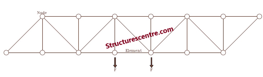
- Point loads should as much as possible be applied only at the nodes, except under stringent conditions.
- Joints should be detailed to allow all applied & internal forces to be concentric with the steel connections.
Action on Steel Trusses
The actions a steel truss will be required to sustain will depend on the intended function/use of the steel truss. For example, roof trusses in most instances are required to sustain dead, imposed wind and even snow actions whereas a transfer truss may only be required to sustain only dead and imposed actions.
Generally, the loads that can be found on a steel truss are:
Permanent (Dead) Actions: The permanent actions include all dead loads applied on the steel truss, including the self-weight of the truss and any additional steel element. In the case of a roof truss, the permanent actions will consist of the load from the roof cladding, self-weight of the steel elements (truss members and purlins) and the applied loads from finishes.
Variable Actions: Variable actions include all loads applied on the truss that varies in magnitude with time. This includes, imposed loading, wind actions and snow actions. Procedure for derivation can be found in the N.A of Eurocode 1.
Steel Sections for Trusses
Many steel sections are applicable for use as steel truss member. However, the choice will depend on factors ranging between the magnitude of the internal forces, ease of doing the connections, aesthetics and fabrication constraints.
For smaller spans, Double angle or Tee sections are used for the chords and internal members, with the connections being either bolted or welded. With increase in span, or heavier loads, a channel section might become more appropriate with gusset plates at the nodes to connect the members.
In heavily loaded steel trusses such as those used in steel bridges and those found in buildings where they are used as transfer structure, the magnitude of the internal forces would necessitate rolled sections be used. Typically, UKC & UC sections are used and the nodes are often welded. Any connection necessitated by fabrication is completed with bolted spliced connections.
Where steel trusses are to be exposed in buildings, aesthetics becomes much of a big deal. Hollow steel sections are often chosen for their structural efficiency and aesthetic feel. Similar to UKC & UC sections, their Joints are welded and as part of verifying the member resistance, the resistance of the connections must be verified in accordance with BS EN 1993-1-8 as this might dominate member selection and final geometry.
Design of Steel Members
The design of the truss involves analyzing the truss under the system of loads using statics- either by using the method of joints or sections to obtain the internal forces in the members and then verifying a trial section for adequacy.
In the analysis and design of steel trusses, although it is assumed that the joints in steel trusses are pinned, this is seldom true. The joint thus have some form of rigidity. This follows that some form of bending moment and shear forces would be induced in the steel members. However, for the purpose of simplicity, it is generally satisfactory and even encouraged by design codes to assume that the joints are pinned and hence only verify these members for axial loads only. The assumption on pinned joints is valid regardless of whether bolted or welded connections is used.
Where loads are applied between nodes, bending moment and shear forces will be induced regardless of the pinned joints. Thus, the truss chords are idealized as a continuous beam member and then analyzed for bending moment, shear and axial force while the internal members are analyzed for axial forces only. In any case the truss nodes are still assumed fully pinned.
Verification of Members in Tension
For a truss member in axial tension under a uniaxial stress state, Clause 6.2.3(1) of BS EN 1993-1-1 gives an expression that must be satisfied. This is defined as:
\frac { { N }_{ Ed } }{ { N }_{ t,Rd } } \le 1.0Where: NEd is the design tensile force. Nt, Rd is the design tension resistance, how to determine it value has been defined in a previous article. See “Design of Steel Elements in Tension to Eurocode”.
Verification of Members in Compression
For truss members in compression, evaluating the member resistance is slightly more complicated, the different modes of instability must be taking into consideration. In most truss members in axial compression, only flexural buckling in the plane and out of the plane of the truss would need to be verified. This buckling resistance is obtained by applying a reduction factor to the resistance of the cross-section. This reduction factor is obtained from the slenderness of the member which depends on the elastic critical force. This is defined in Clause 6.3.1.1(1) as:
\frac { { N }_{ Ed } }{ { N }_{ b,Rd } } \le 1.0Where, Nb,Rd is the design buckling resistance of the compression member. The expression for determining it value has been defined in a previous article. See “Design of Steel Elements in Axial Compression to EC3”.
In determining the reduction factor, the buckling length of the member need to be determined, this depends on the whether the buckling is occurring in the plane or outside the plane of the truss.
- For buckling in the plane of the truss, the buckling length is taken equal to 90% of the system length (distance between nodes)
- For buckling outside the plane of the truss, the buckling length is equal to the system length
For chord members under the combined actions of bending and axial compression, verification of the member is tedious and outside the scope of this article. However, guidance can be obtained from BS EN 1993-1-1.
Worked Example
The figure shown below is a part plan of a mono-pitch roof over the gallery of a large church building. In-order to provide an uninterrupted clear span, the use of steel trusses has been recommended as the most viable structural solution. Produce enough hand calculations to establish the form and size of the members in (Truss 1). The design is to be carried out in S275 Steel, E =200Gpa
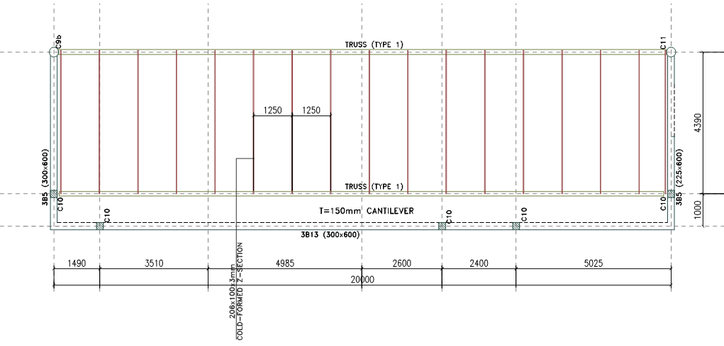
By inspection the roof truss would be predominantly under the influence of gravitational actions, hence a Pratt Truss would give the most effective solution.
Actions
Permanent Actions
- Self-weight of roof cladding (0.6mm sheets) =0.022kN/m2
- Self-weight of purlins & Truss members =0.4kN/m2
- Services & finishes say =0.3kN/m2
Permanent Actions gk= 0.772kN/m2
Variable Actions (Imposed)
The roof is inaccessible except during maintenance and repairs, thus from Table 6.9 of BS EN 1991-1-1:2001
- Imposed load qk = 0.75kN/m2
Variable Actions (Wind)
Wind action has been determined according to the recommendations of BS EN (1991 (Part 4). For the sake of simplicity, the detailed calculation is not presented here.
- Overall wind load wk = -1.2kN/m2
Structural Analysis
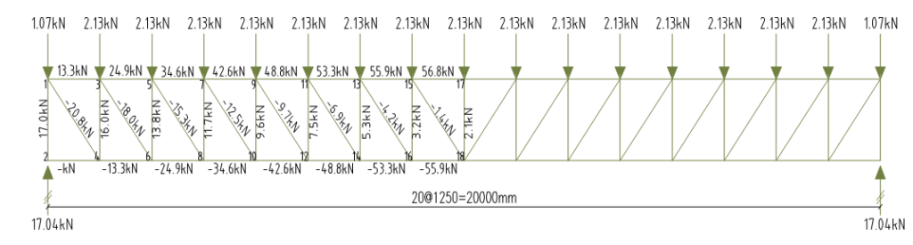
Permanent Actions
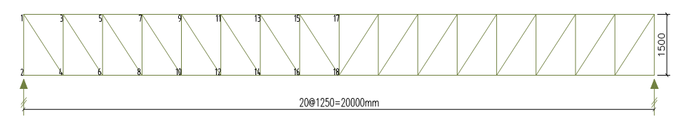
The permanent action is first converted from pressure to uniformly distributed loading on the purlins, the vertical reaction from the purlins is then determined and applied to the nodes of the steel truss. The truss is then analyzed for the internal forces using either the method of joints or sections. Only the axial forces are presented here.
It should be noted that at the first and last nodes, the loads are always halved since the tributary load width would be half the value (1.25/2).
The sign convention for the internal forces is positive for axial compressive forces and negative for tensile forces
Load transferred to purlins = 0.772 × 1.25 =0.97kN/m
Vertical Reaction Gk = 0.5×0.97×4.39 = 2.13kN
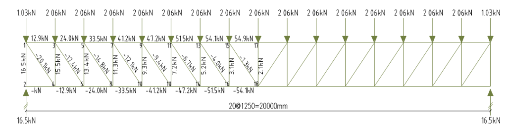
Variable Actions (Imposed)
Similar procedure as in permanent actions is followed here.
Load transferred to purlins = 0.75 × 1.25 =0.94kN/m
Vertical Reaction Qk = 0.5×0.94×4.39 = 2.06kN
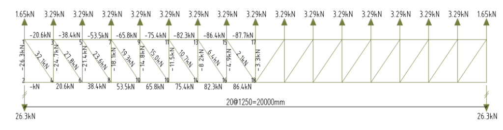
Variable Actions (Wind)
The negative value of the wind pressure, indicates suction and not pressure, hence there would be stress reversal in the members. The nodal point load is determined in a similar fashion.
Load transferred to purlins = -1.2 × 1.25 =-1.5kN/m
Vertical Reaction Wk = 0.5×1.5×4.39 = -3.29kN
Design Forces
In determining the design value, partial factors are applied to the internal forces based on the associated load-cases. Two load combinations will be considered:
- (Permanent Actions + Variable Imposed Actions)
- (Permanent Actions + Variable Wind Actions)
By inspection load case one appears to be the most critical combination. However, load combination two would almost always cause stress reversal hence should at all times be checked.
Table 1 Structural Analysis & Design Values.
| Element | Perm. Action | Variable Imp. Action | Variable Wind Action | Combination 1 (1.35Gk +1.5Qk) | Combination 2 (1.35Gk +1.5Wk) | Length (mm) |
| 1-3 | 13.3kN(c) | 12.9kN(c) | 20.6kN(t) | 37.3kN(c) | 12.9kN(t) | 1250 |
| 3-5 | 24.9kN(c) | 24.0kN(c) | 38.4kN(t) | 69.6kN(c) | 24.0kN(t) | 1250 |
| 5-7 | 34.6kN(c) | 33.5kN(c) | 53.5kN(t) | 97.0kN(c) | 33.6kN(t) | 1250 |
| 7-9 | 42.6kN(c) | 41.2kN(c) | 65.8kN(t) | 119.3kN(c) | 41.2kN(t) | 1250 |
| 9-11 | 48.8kN(c) | 47.2kN(c) | 75.4kN(t) | 136.7kN(c) | 47.2kN(t) | 1250 |
| 11-13 | 53.3kN(c) | 51.5kN(c) | 82.3kN(t) | 149.3kN(c) | 51.5kN(t) | 1250 |
| 13-15 | 55.9kN(c) | 54.1kN(c) | 86.4kN(t) | 156.7kN(c) | 54.1kN(t) | 1250 |
| 15-17 | 56.8kN(c) | 54.9kN(c) | 87.7kN(t) | 159.0kN(c) | 54.9kN(t) | 1250 |
| 2-4 | 13.3kN(t) | 12.9kN(t) | 20.6kN(c) | 37.3kN(t) | 12.9kN(c) | 1250 |
| 4-8 | 24.9kN(t) | 24.0kN(t) | 38.4kN(c) | 69.6kN(t) | 24.0kN(c) | 1250 |
| 8-10 | 34.6kN(t) | 33.5kN(t) | 53.5kN(c) | 97.0kN(t) | 33.6kN(c) | 1250 |
| 10-12 | 42.6kN(t) | 41.2kN(t) | 65.8kN(c) | 119.3kN(t) | 41.2kN(c) | 1250 |
| 12-14 | 48.8kN(t) | 47.2kN(t) | 75.4kN(c) | 136.7kN(t) | 47.2kN(c) | 1250 |
| 14-16 | 53.3kN(t) | 51.5kN(t) | 82.3kN(c) | 149.3kN(t) | 51.5kN(c) | 1250 |
| 16-18 | 55.9kN(t) | 54.1kN(t) | 86.4kN(c) | 156.7kN(t) | 54.1kN(c) | 1250 |
| 1-2 | 17.0kN(c) | 16.5kN(c) | 26.3kN(t) | 47.7kN(c) | 16.5kN(t) | 1500 |
| 3-4 | 16.0kN(c) | 15.5kN(c) | 24.7kN(t) | 44.9kN(c) | 15.5kN(t) | 1500 |
| 5-6 | 13.8kN(c) | 13.4kN(c) | 21.1kN(t) | 38.7kN(c) | 13.1kN(t) | 1500 |
| 7-8 | 11.7kN(c) | 11.3kN(c) | 18.1kN(t) | 31.1kN(c) | 11.4kN(t) | 1500 |
| 9-10 | 9.6kN(c) | 9.3kN(c) | 14.8kN(t) | 26.9kN(c) | 9.2kN(t) | 1500 |
| 11-12 | 7.5kN(c) | 7.2kN(c) | 11.5kN(t) | 20.9kN(c) | 7.2kN(t) | 1500 |
| 13-14 | 5.3kN(c) | 5.2kN(c) | 8.2kN(t) | 15.0kN(c) | 5.1kN(t) | 1500 |
| 15-16 | 3.2kN(c) | 3.1kN(c) | 4.9kN(t) | 9.0kn(c) | 3.0kN(t) | 1500 |
| 17-18 | 2.1kN(c) | 2.1kN(c) | 3.3kN(t) | 6.0kN(c) | 2.1kN(t) | 1500 |
| 1-4 | 20.8kN(t) | 201.kN(t) | 32.1kN(c) | 58.3kN(t) | 20.1kN(t) | 1953 |
| 3-6 | 18.0kN(t) | 17.4kN(t) | 27.8kN(c) | 50.4kN(t) | 17.4kN(t) | 1953 |
| 5-8 | 15.3kN(t) | 14.8KN(t) | 23.6kN(c) | 42.9kN(t) | 14.7kN(c) | 1953 |
| 7-10 | 12.5kN(t) | 12.1kN(t) | 19.3kN(c) | 35.1kN(t) | 12.1kN(c) | 1953 |
| 9-12 | 9.7kN(t) | 9.4kN(t) | 15.0kN(c) | 27.2kN(t) | 9.4kN(c) | 1953 |
| 11-14 | 6.9kN(t) | 6.7kN(t) | 10.7kN(c) | 19.4kN(t) | 6.8kN(c) | 1953 |
| 15-18 | 4.2kN(t) | 4.0kN(t) | 6.4kN(c) | 11.7kN(t) | 3.9kN(c) | 1953 |
| 13-16 | 1.4kN(t) | 1.3kN(t) | 2.1kN(c) | 3.8kN(t) | 1.3kN(c) | 1953 |
To view the Full article including the design of the truss members please click here
Citations & Further Reading
- Steel Construction Institute – Single storey buildings Part 5: Detailed Design of Trusses.
- BS EN 1993: Design of steel structures – Part 1-1: General rules and rules for buildings
- U.K National Annex to BS EN 1993: Design of steel structures – Part 1-1: General rules and rules for buildings.