In buildings with stringent span requirement with vertical element discontinuities, transfer trusses perform better than transfer beam and transfer plates.
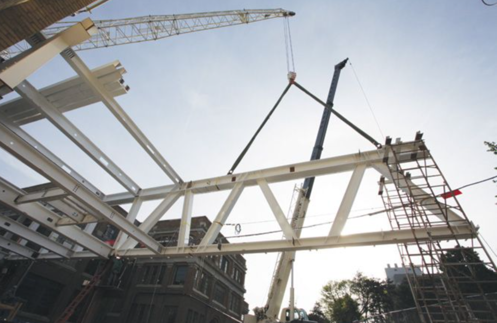
A transfer truss is simply a triangulated assembly of interconnected elements, pinned at the nodes. Transfer trusses when compared to traditional transfer beams are relatively a more efficient way of dealing with vertical element discontinuities. It comes down to the typical advantages a truss has over other plane members. Trusses are lightweight, they can carry considerably more gravity loads, while being able to span longer. This is primarily valuable for transition structures, as most transition structures are heavily loaded and required to span over longer distance.
Also, by virtue of trusses being open web structures, they integrate better with architectural and mechanical systems than transfer beams. Indeed, the components of the truss may be made so slender that they can be integrated into standard residential or commercial layouts by simply increasing the truss depth to a certain number of stories. The value of the net internal areas much outweighs the structural cost differences, which is an important component of a transition structure’s benefit.
Designing a Transfer Truss
To design a transfer truss, the load from the discontinuous vertical element is first estimated. This load is then applied on the truss whose form must be selected such that all longer members are in tension while the shortest members are in compression. For instance, for transfer structures, a “Pratt” is favoured over a “Howe,” since transfer structures are mainly required to transmit gravity loads only (See: Structural Aspects of Selecting a Plane Truss).
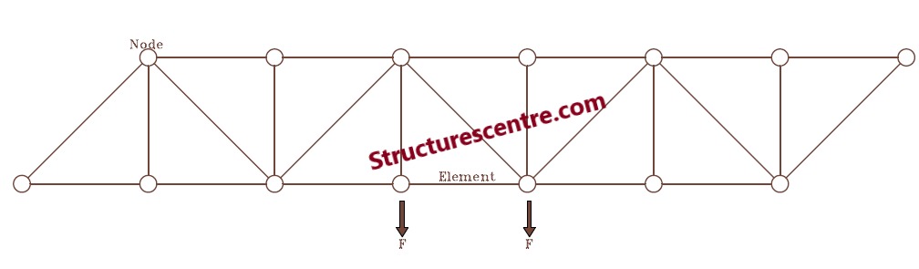
Having obtained the loads from the vertical element and also selected a viable and economical form for the truss, the truss must be analyzed to determine the design forces. In trusses, loads from the vertical elements are typically applied at the nodes only. Thus, the designer is safe to assume that all members only resist axial actions only. However, if there is any application of load directly on a member of the truss, the resulting bending moment on the members should be determined and used alongside the axial forces for member verification. For many transfer trusses, the method of joints/method of sections will be sufficient to obtain the design forces required for member sizing.
The next step is to select trial sections and verify their resistances to the design forces determined above. For members in tension, the tension resistance governs and is used for verification (See: Design of Steel Elements in Tension to Eurocode). For members in compression, the flexural buckling resistance might govern (See: Design of Steel Elements in Axial Compression to EC3). Where a member is resisting both bending and tension/compression, the combined resistance is used for the member verification (See: Steel Columns in Combined Axial Compression and Bending).
With respect to sections, transfer trusses are typically fabricated out of steel and because they are heavily loaded, the magnitude of the internal forces normally necessitate rolled sections be used. Typically, UKC & UC sections are used, and the nodes are often welded. Any connection necessitated by fabrication is completed with bolted spliced connections.
Finally, the deflection of the truss needs to be verified for compliance with serviceability. For transfer trusses, deflection is arguably one of the most critical considerations. To determine the overall deflection of the beam the truss must be idealized as a beam. For instance, where the truss is simply supported, the deflection of the truss is determined as if the truss was a simply supported beam, while if it’s a cantilever, the deflection is determined as though the truss was a cantilever beam. In estimating deflection, the second moment area for the entire truss must be determined, this is done by applying the parallel axis theorem.
Worked Example
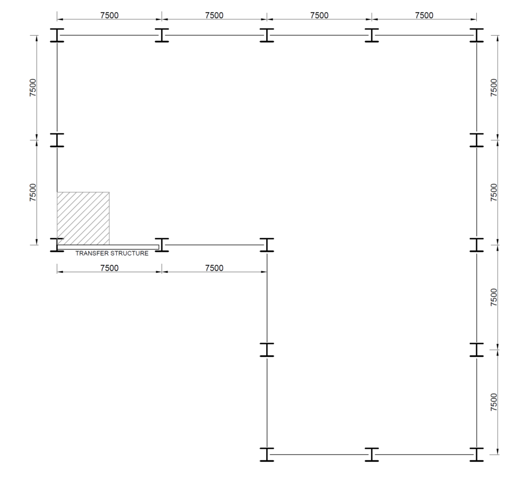
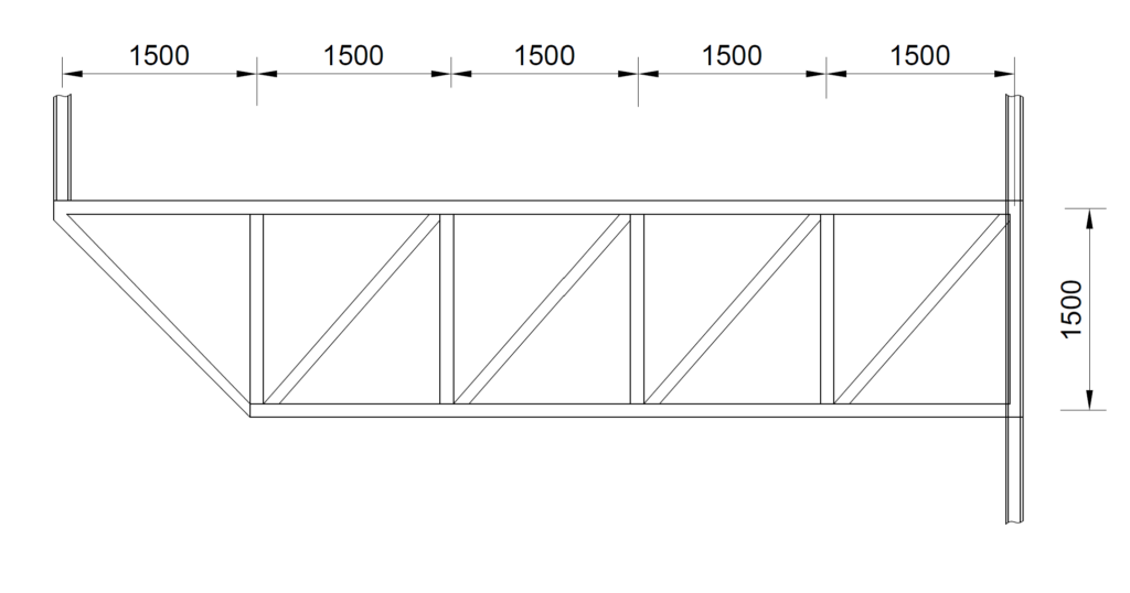
Figure 2 shows the typical structural G.A of an 8-storey office block. A 7.5m transition structure is required to transfer the loads from an edge column to a neighboring column. A transition truss has been proposed to transmit the loads (Figure 3). Carry out sufficient hand calculation to size the members of the transition truss, assuming the floor is loaded with 6kN/m2 and 3kN/m2 in permanent and variable actions respectively. Use S275 Steel.
Actions
We begin by determining the total actions on the transfer column at the level of the transfer truss. To do this, we must first determine the design actions on the floor and then multiply the value by the tributary area of the transfer column.
Design Value of Actions on Floor
n_s = 1.35g_k +1.51_k
= (1.35\times 6 )+(1.5\times 3.0) =12.6kN/m^2
Tributary Area
A_T=\frac{7.5}{2} \times \frac{7.5}{2} = 14.1m^2Design Value of Actions on Column/Floor
Floor=12.6 \times 14.1 =177.7kN
Column = 20kN
= 177.7 + 20 =197.7kN
Design Value of Actions at Transfer Truss Level
= 8\times 197.7 =1581.6kN
N_{Ed} = 1582kNAnalysis of Truss
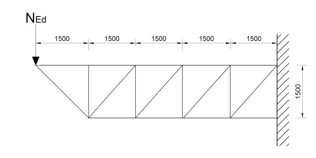
For analysis, the truss is idealized as a cantilever (Figure 4). And since, the truss is a cantilever the maximum tensile and compressive force will occur in the members closest to the support. Also, because the truss is a Pratt the vertical members are in compression while the tensile members are in compression with an exception to the diagonal member directly connected to the transfer column which acts as a strut.
By inspection of the free body diagram above and since maximum tensile and compressive force occurs in members closest to the cantilever support, we can use their design forces to size all members of the truss as this would be conservative. To do this, we cut a section through the cantilever region and use the method of sections to obtain the design forces (Figure 5).
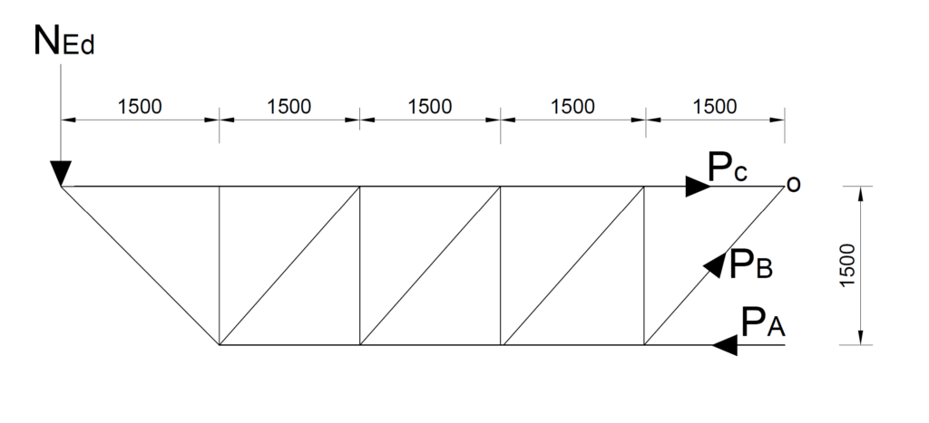
We can apply the three equations of statics to the free body diagram above to obtain the design forces; PA; PB and PC.
\sum M_o =0
1582 \times 7.5 -P_A\times1.5 = 0
P_A=\frac{1582\times7.5}{1.5} =7910kN(c)\sum F_y =0
-1582+P_Bsin45 = 0
P_B = 2237kN(t)
\sum F_x=0
-P_A+P_Bsin\cos\theta +P_C= 0
P_C=7910-2237\cos45 = 6328kN (t)
Truss Member Verification
Having obtained the design forces, the next procedure is to select steel sections and determine the resistances of each member. However, for simplicity, we have created two design groups. The first being the top and bottom chord and the second being the verticals and diagonals (See Table 1).
| Members | NEd,c (kN) | NEd,t (kN) |
| Top & Bottom Chord | 7910 | 6328 |
| Diagonal & Vertical | 2237 | 2237 |
Since each design group now has a compressive force, thus compression buckling is most likely to control each design group. Hence this is the only verification that is conducted here. It is expected that the tensile resistance would always be higher.
A) Top & Bottom Chord
NEd,c = 7910 kN NEd,t = 6328 kN L = 1500mm
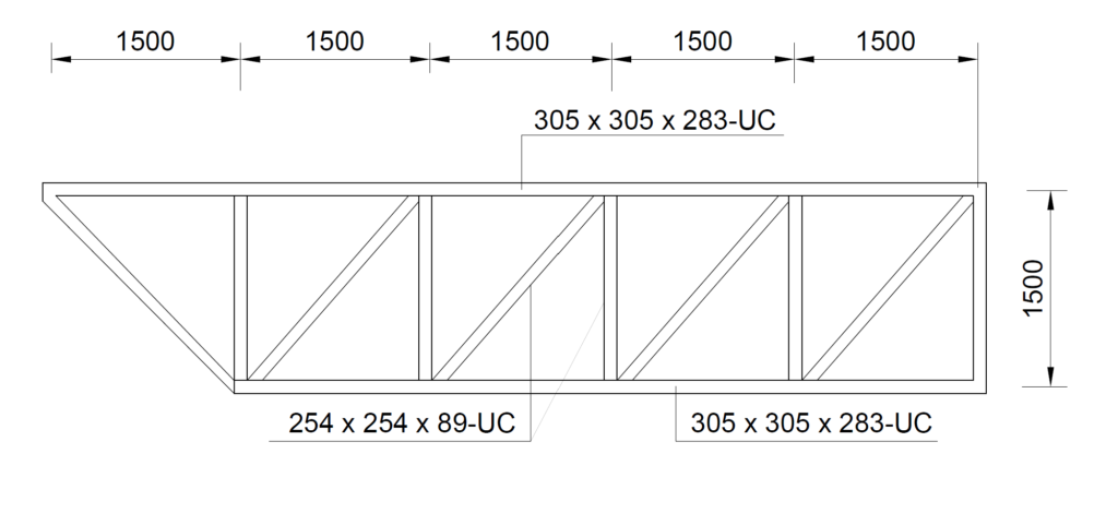
Try a 305 x 305 x 283 UC- SECTION
h = 365.3mm; b=322.2mm; tw = 26.8mm; tf= 44.1mm; r = 15.2mm; d =246.7mm; A=360cm2; Iyy = 78900cm4; Izz =24600cm4; iyy=14.8cm; izz=8.27cm; E=210kN/mm2; fy = 255N/mm2
Flexural Buckling Resistance – Critical
\frac { { N }_{ Ed,c } }{ { N }_{ b.Rd } } \le 1.0{ N }_{ b,Rd }={ N }_{ b,z,Rd }=\chi_z \frac { A{ f }_{ y } }{ { \gamma }_{ M1 } } Verify Buckling
\lambda_z =\frac { { L }_{ cr } }{ i_{zz} } \cdot \frac { 1 }{ 86 } =\frac { 1500}{ 82.7 } \cdot \frac { 1 }{ 86 }=0.21 For hot finished I- section, buckling curve c applies, hence α=0.49
\phi_z =\left[ 0.5+\alpha \left( \lambda_z -0.2 \right) +{ \lambda_z }^{ 2 } \right] =0.5\left[ 1+0.49\left( 0.21-0.2 \right) +{ 0.21 }^{ 2 } \right] =0.52\chi_z =\frac { 1 }{ \phi_z +\sqrt { { \phi_z }^{ 2 }-{ \lambda_z }^{ 2 } } } =\frac { 1 }{ 0.52+\sqrt { { 0.52}^{ 2 }-{ 0.21}^{ 2 } } } =0.99\le 1{ N }_{ b,Rd }==0.99\times \frac { 36000\times 255 }{ 1.0 } =9088.2kN\frac { { N }_{ Ed,c } }{ { N }_{ b.Rd } }=\frac{7910}{9088.2}=0.87 \le 1.0 \quad o.kA) Diagonals & Verticals
NEd,c = 2237 kN NEd,t = 2237 kN L = 2121mm
Try a 254 x 254 x 89 UC- SECTION
h = 260.3mm; b=256.3mm; tw = 10.3mm; tf= 17.3mm; r = 12.7mm; d =200.3mm; A=113cm2; Iyy = 14300cm4; Izz =4860cm4; iyy=11.2cm; izz=6.55cm; E=210kN/mm2; fy = 265N/mm2
Flexural Buckling Resistance – Critical
\frac { { N }_{ Ed,c } }{ { N }_{ b.Rd } } \le 1.0{ N }_{ b,Rd }={ N }_{ b,z,Rd }=\chi_z \frac { A{ f }_{ y } }{ { \gamma }_{ M1 } } Verify Buckling
\lambda_z =\frac { { L }_{ cr } }{ i_{zz} } \cdot \frac { 1 }{ 86 } =\frac { 2121}{ 65.5 } \cdot \frac { 1 }{ 86 }=0.37 For hot finished I- section, buckling curve c applies, hence α=0.49
\phi_z =\left[ 0.5+\alpha \left( \lambda_z -0.2 \right) +{ \lambda_z }^{ 2 } \right] =0.5\left[ 1+0.49\left( 0.37-0.2 \right) +{ 0.37 }^{ 2 } \right] =0.61\chi_z =\frac { 1 }{ \phi_z +\sqrt { { \phi_z }^{ 2 }-{ \lambda_z }^{ 2 } } } =\frac { 1 }{ 0.61+\sqrt { { 0.61}^{ 2 }-{ 0.37}^{ 2 } } } =0.92\le 1{ N }_{ b,Rd }==0.92\times \frac { 11300\times 265 }{ 1.0 } =2755kN\frac { { N }_{ Ed,c } }{ { N }_{ b.Rd } }=\frac{2237}{2755}=0.81 \le 1.0 \quad o.kDeflection of Truss
Actual Deflection
For a cantilever structure receiving a point action at its free end, just as we have in this transfer truss, the maximum deflection is at its free end. The value can be obtained from the following expression:
\delta_{max}=\frac{Pl^3}{3EI}Where P is the design load at serviceability limit state. However, for simplicity the point load derived earlier with the partial factors will be utilized. Hence:
P = N_{Ed}=1582kNNote that the second moment area for the entire truss must be determined based on the parallel axis theorem. This is derived using the following expression:
I_{truss}=2I_{chords}+2A_{chords}y^2=2(78900)+2\times360\times(150/2) \\=4207.8\times10^3cm^4
\delta_{max} =\frac{1582\times10^3\times7500^3}{3\times210\times10^3\times 4207.8\times10^7}=25.2mm
Deflection Limit
\delta_{limit} =\frac{span}{180} =\frac{7500}{180} =41.7mmSince the actual deflection of the truss is less than the deflection limit, the members are satisfactory.
See: Structural Analysis and Design of Transition Structures
Design Resume