Transfer structures are used in buildings with vertical element discontinuities and where a direct load passage to the foundations is not practicable. This article offers an overview of the various types of transfer structures employed in building structures as well as guidance on their design and construction.
A transfer or transition structure is a crucial structural element that facilitates the transfer of loads, forces or functions from one part of a structure to another.
Many times, in the design of building structures, functionality, aesthetics and often planning requirement will necessitate the need for changes or discontinuities in the vertical load bearing system. These needs frequently occur outside the bounds of conventional structures, resulting in unique and intriguing technical difficulties that is typically handled using some sort of transfer or transitional structure2.
In other words, a transition structure provides a means of redirecting gravity loadings when a vertical supporting member (typically columns) has to be interrupted and a direct load path to the foundation is impossible. For instance, consider there is the need to transfer the loads from some columns at the upper floors of an Highrise building to the foundation, but the columns cannot go through the ground floor, because there is the requirement of a large hall which must be columns free. Hence, a transition structure is provided to redirect the loads to away to the neighbouring supporting members.
These days it is increasingly difficult to come across a structural scheme that doesn’t require some form of transition structure. Whether it’s a mixed-use building that provides for two or more types of occupancies or it’s a high-rise commercial building with a requirement of large column-free spaces at the lower floors. It follows therefore that structural engineers must be aware of the options that are available.
Transition structures by virtue of the role they perform are almost always made up of massive concrete or steel elements that occupies a lot of space within structures. Where the gravity loads expected are so large such as in tall buildings, they may even go as deep as a storey. Hence, there is the need to follow a holistic approach to their design.
As stated, the primary function of a transition structure is to ensure a continuous transfer of gravity loads to the foundation; they are not part of the lateral load resisting system of a structure hence are not explicitly designed to resist lateral loads. However, because they are very stiff structural elements, they tend to attract considerable lateral forces. Hence it might sometimes make sense to integrate them with the lateral stability system.
Types of Transitional Structures
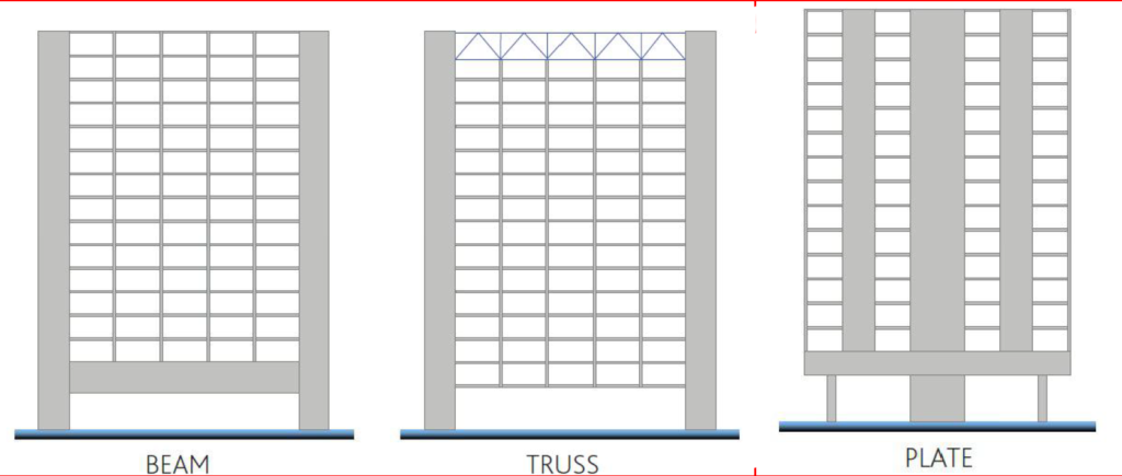
There are several types of transition structures that can be found in structures. However, those commonly found in buildings can be rationalized into three generic forms. These include the transfer beam, transfer truss and the transfer plate. All forms are supported by reinforced concrete and structural steel and sometimes prestressed concrete. The form of transfer to use for any given scheme is dependent on a range of factors which the structural engineer must investigate. More of this in the next sections.
Transition Beams
Out of the three forms of transition structures itemized above, the transfer beam is the most basic and most common form of transition structures. Even in conventional structures, it is quite common that a column cannot go all the way to it foundations. Thus, the load arising from the particular column is transferred to the neighbouring ones. One of the methods by which this is achieved is through a beam, in this case a transfer beam.
Transfer beams are the most basic and most common form of transition structures, common because of their simple design methodology and construction. To design a transfer beam, where a column is discontinuous to the foundation for instance, the load from the column is estimated, as if it were to be supported by a foundation. Then this estimated load is considered as an axial action on the transfer beam. This normally culminates in high bending moments and shearing forces than would not normally be expected in a conventional flexural element. Hence, while a transition beam is in fact a beam, they are often characterized by unusual depth due to the often-extra-large design forces they must resist.
In terms of material, transfer beams can be made from either steel or reinforced concrete. When they are constructed in reinforced concrete, they are usually of greater depth requiring substantial volume or rebars. Sometimes, where the volume of rebars is so large, pre-stressing, may be employed.
Transition Truss
Following closely after the transition beam are the transition trusses. Relative to transition beams, transition trusses are better because they are primarily lightweight can carry considerably more gravity loads for the equivalent transition beam section, while being able to span longer. Also, by virtue of trusses being open web structures, they integrate better with architectural and mechanical systems than transfer beams. In fact, by just raising the truss depth to a specific number of stories, the components of the truss become so thin that they may be incorporated into normal residential or commercial layouts2. The greatest advantage of this form of transition structure is that the value of the net internal areas greatly overcomes the structural cost disparities.
The transition truss concept is of two types: the transfer truss and the hanger. The first is a standard truss, which typically spans across RC walls or columns and receives weight from the discontinued columns at node points. The hanger transfer structure, on the other hand, is likewise made up of axially loaded elements, which is a simplified version of a normal truss since it only has an inclined member in tension and a bottom horizontal element in compression.
Similar to a transition beam, the design of a transfer truss also requires estimating the loads from the columns that is to be supported and then applying the same to the transfer truss. Analysis of the truss is then carried out to determine the design forces in the truss members. Most trusses are constructed with structural steel; transition trusses are no different.
See: Design of Steel Trusses to Eurocode
Transition Plate
A transfer plate is a thick reinforced concrete slab that can redirect loads in more than one direction. They are quite an unusual transition structure that is designed when there is a radical change in a building grid that almost completely alters load paths. For instance, where there are too many columns that are discontinuous across a level; why not just place them on the floor and design the floor to carry the loads?! Designing a transition plate offers the architect and structural engineer a lot of freedom to alter the supporting system and the vertical load paths.
Transfer plate is most often the last resort, after which a transfer beam or transfer truss must have been considered but fails to provide an economical/viable solution. They are mostly found in tall buildings where the transfer plate is often installed between the tower and a podium, 20 to 30 meters above ground level. The top floors are frequently used to house offices or residential units, whilst the podium floors are used to house various functional spaces such as a retail mall or a lift lobby, which require big column-free rooms.
Buildings with a transfer plate are often include a shear wall system in the top structure, mega-columns below the transfer floor, and a central core as the sole continuous vertical feature. As a result, the transfer plate unquestionably contributes to the lateral load resisting system, as some of the transferred elements may attract considerable lateral loads.
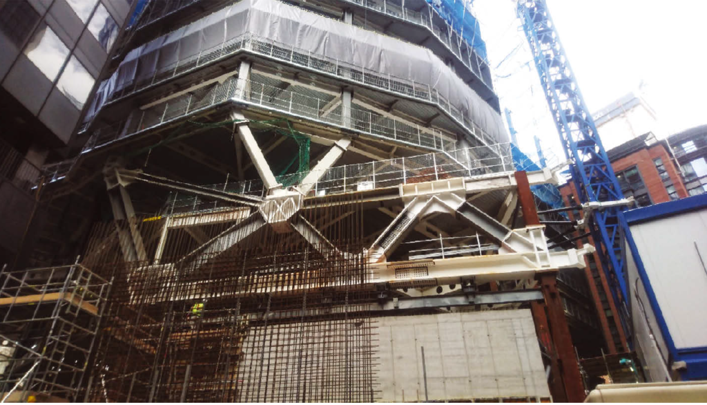
Also, because a transfer plate often stretches the whole building footprint and can be several meters thick, it is a gigantic concrete structure with a significant self-weight and extensive reinforcing, as depicted in Figure 8. Thus, as concluded for transfer beams, post-tensioning a transfer plate is also an efficient method of decreasing reinforcing steel and plate thickness while enhancing cracking and deflection performance. The reduction in plate thickness, and hence in self-weight, is also beneficial to the falsework system, which should support a lighter structure.
Finally, the design of transition plate is not so straightforward and complicated because analysis requires modelling bending of the plate in two orthogonal directions. However, there are several software that can be used for analysis and design.
Key Considerations in the Design of Transition Structures
Transition structures are not conventional structural elements, therefore there must be some consideration that are peculiar to them.
Out of all the parameters for design of transition structures, deflection is the most critical. Transition structure is prone to substantial deflections due to their lengthy spans and the magnitude of the forces involved, the design for deflection control is generally the primary concern. It’s also the parameter that determines the size of a transition element.
Because of the wide variation in vertical stiffness and mobilized mass, some transfer structures are very vulnerable to vertical excitations. As a result, the impacts of human-induced vibrations must be managed, and the vertical component of seismic activity becomes even more important, which is uncommon in building constructions.
In seismic zones, the conceptual design of buildings with global transfer structures must be carefully designed to guarantee that the transfer structure does not risk or damage the seismic design of the building. Code-prescriptive design approaches for the seismic design of the transfer structure may not be adequate for complicated structural systems. Non-linear time-history assessments as part of a Performance Based Design method are advised, since they can demonstrate acceptable transfer structure behavior by demonstrating that it stays elastic even during big seismic occurrences.
Finally, one of the biggest challenges with transition structures have to do with the logistical construction issues they present due to heavy element sequencing and installation, as well as formwork complications. Due to the weight of transition structure elements, they tend to require temporary support systems which are very vital in the building process and can have a significant impact on the total value of a solution.
Worked Example
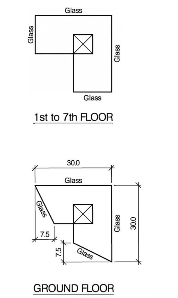
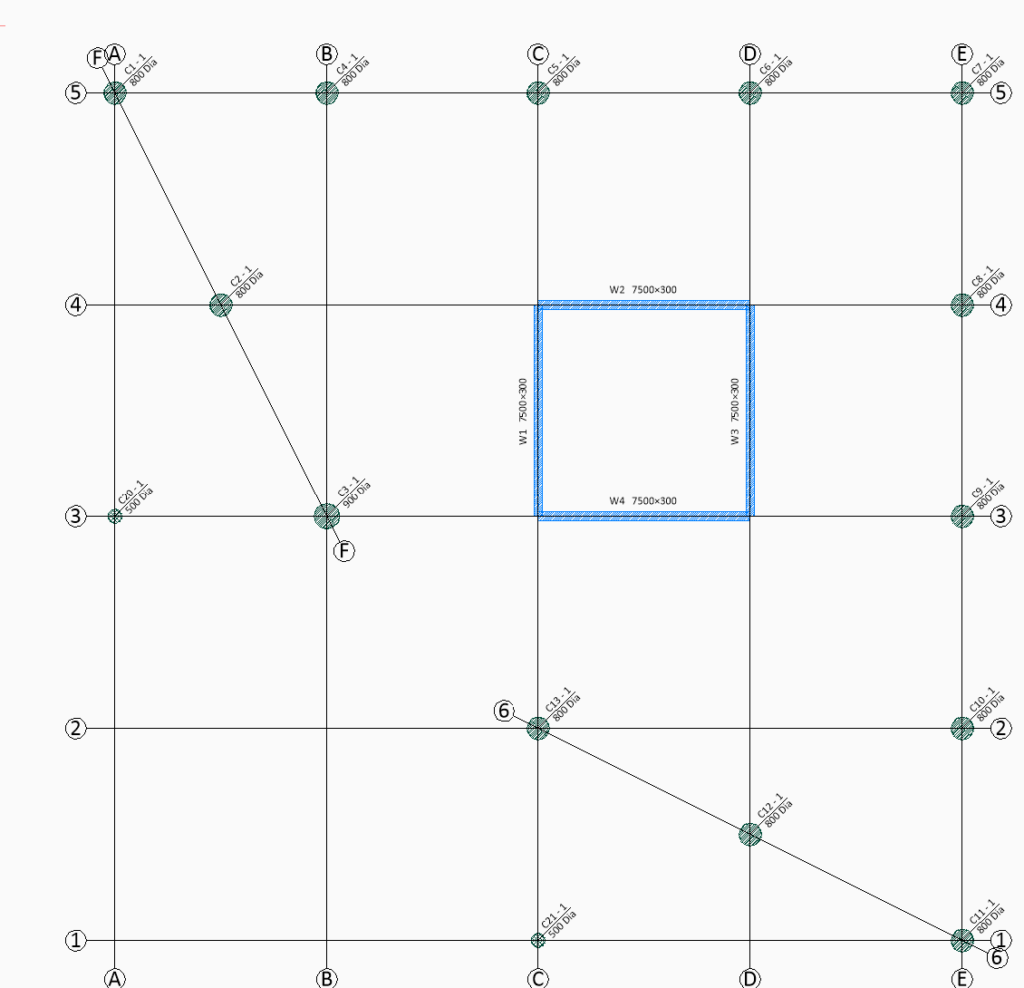
Figure 2 shows the architectural floor plan of an 8-storey office block and Figure 3 shows the structural G.A at first floor level. It can be seen that a transition structure is required at first floor level to transfer the loads from columns C20 & C21 to the neighboring columns C3 & C13. Design a transition beam to transfer the load. Assuming the action actions from columns C20 & C21 are 430kN and 198kN permanent and variable actions respectively. Use C25/30 concrete and 460Mpa steel bars.
Preliminary Sizing of Beam
\frac{L}{5} = \frac{7.5}{4.5} =1.67m Try 500 x 1750mm upstand beam.
Actions
The design action on the beam includes the loads from the floor slab being supported, the self-weight of the beam and axial action from the transfer column. However, for the sake of simplicity, only the axial action from the column will be considered.
F_d =1.35G_k +1.5Q_k\\=(1.35\times430) +(1.5\times198) =877.5kN
Structural Analysis
The transfer beam can be idealized as a 7.5m cantilever. Thus, the maximum bending moment and shear force occurs at the support and can be obtained as follows:
Bending Moment
M=F_d\times l =877.5\times 7.5 =6581kN.m
Shear Force
V = F_d =877.5kN
Flexural Design
M_{Ed}=6581kN.mAssuming 40mm bars in two layers and concrete cover of 40mm and 12mm links, we can determine the effective depth for design as:
{ d }=h-(c+\phi /2)\\=1750-(40+40/2+40+12)=1648mm
b =b_w+\frac{l}{5.5} =500+\frac{7500}{15} = 1000k=\frac { { M }_{ Ed } }{ b{ d }^{ 2 }{ f }_{ ck } } =\frac { 6581\times { 10 }^{ 6 } }{ { 500}\times { 1648}^{ 2 }\times 25} =0.194z=0.78d=0.78\times 1648=1285.44mm
{ A }_{ s }'=\frac { { (k-k')bd^2f_{ck} } }{ 0.87{ f }_{ yk } (d-d') }{ A }_{ s }'=\frac { { (0.194-0.168)\times 500\times 1648^2 \times 25} }{ 0.87\times 460\times (1648-72) }\\ = 1399.4mm^2{ A }_{ s }=\frac { { k'bd^2f_{ck}} }{ 0.87{ f }_{ yk }z } +A_s' =\frac { 0.168\times500\times1648^2\times 25}{ 0.87\times 460\times 1285}+1399.4 \\=12490{ mm }^{ 2 }/mUse 11T40mm bars -Top (As, prov = 13824.8mm2)-Two layers
Shear Design
By inspection, the shear force in the beam is relatively low for the design chosen beam section. Hence minimum area of shear reinforcement based on detailing requirements may be provided.
Deflection Verification
{ \left[ \frac { l }{ d } \right] }_{ limit }\ge{ \left[ \frac { l }{ d } \right] }_{ actual }Limiting L/d Ratio
{ \left[ \frac { l }{ d } \right] }_{ limit }=N\cdot k\cdot F1\cdot F2\cdot F3\rho =\frac { { A }_{ s,req } }{ bd } =\frac { 12490 }{ 500\times 1648 } =0.015\rho' =\frac { { A }_{ s,req }' }{ bd } =\frac { 1399.4 }{ 500\times 1648 } =0.0017{ \rho }_{ o }={ 10 }^{ -3 }\sqrt { { f }_{ ck } } ={ 10 }^{ -3 }\times \sqrt { 20 } =0.005
N=11+\frac { 1.5\sqrt { { f }_{ ck } } { \rho }_{ o } }{ \rho-\rho' } +\frac{\sqrt { { f }_{ ck } }}{12} \frac{\sqrt\rho'}{\sqrt\rho_{o}}N= 14.08
F1=1.0;\quad k=0.4;\quad \\F2=1.0=7/7.5=0.93
F3=\frac { 310 }{ { \sigma }_{ S } } \le 1.5{ \sigma }_{ S }=\frac { { f }_{ yk } }{ { \gamma }_{ s } } \left[ \frac { { g }_{ k }+{ \psi q }_{ k } }{ { n }_{ s,max } } \right] \left( \frac { { A }_{ s,req } }{ { A }_{ s,pro } } \right) \cdot \frac { 1 }{ \delta }=\frac { 410 }{ 1.15 } \left[ \frac { 430+(0.6\times 198) }{ 877.5} \right] \frac { 12490}{ 13824.8} \\=203MpaF3=\frac { 310 }{ 203 } =1.52\le1.5{ \left[ \frac { l }{ d } \right] }_{ limit }=14.08\times 0.4\times 1\times 0.93\times 1.5\\ =7.86Actual L/d Ratio
{ \left[ \frac { l }{ d } \right] }_{ actual }=\frac { 7500 }{ 1648} =4.55Since actual L/d ratio is less than the limiting L/d the beam section is adequate.
Sources & Citations
- Ribeiro, G – “Structural Design of Transfer Structures,” Instituto Superior Técnico, University of Lisbon, 2018 (MSc Thesis).
- Ribeiro, G., Almeida J., and P Labo (2022). “Analysis and construction of transfer structures: a case study” ICSI 2021 The 4th International Conference on Structural Integrity.