This article is concerned with the design of waffle slabs supported on solid column heads – a slab option that combines the benefits of a flat slab in terms of levelled soffits and waffle slabs in terms of savings in concrete and reduced dead loads.
Waffle slabs operates on the same principle as the ribbed floor system, except that in contrast to the standard ribbed slabs, they have ribs in both directions. Hence, why they are normally referred to as two-way slabs.
This article is a sequel to a previous article titled “Designing a Waffle Slab | Worked Example.” It is highly recommended that the reader reviews the previous article at this point before proceeding with this article.
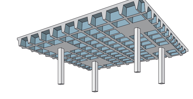
There are two methods by which a waffle slab may be designed based on construction methodology. The first method has the intersecting ribs supported by deep or shallow-band beams which are in turn supported on columns. The second method does without the beams, in which case a solid head over the columns in what looks like a drop panel in typical flat slabs (Figure 1). The purpose of the solid head is to enhance the shear and punching shear resistance which tends to be critical at these points.
Where a waffle slab is supported by beams and it can be demonstrated that these beams provide sufficient torsional stiffness, the slab can be simplistically accepted to be a two-way restrained slab and designed using the coefficient for two-way restrained slab. The design procedure is well covered in the above-referenced article. However, where the ribs are left to span into solid heads over column, the slab is effectively a flat slab and hence the rules governing the design of flat slabs applies. This article is concerned with the latter – design of waffle slabs supported on solid column heads.
Designing Considerations
The design of a waffle slabs supported on column head follows the same procedure as for flat slabs. All rules that govern the design of flat slabs apply, albeit with slight modifications.
Each panel is divided into a column and middle strip. The column strip consists of all the ribs that frame into the solid heads, while the middle strips are typically located in between the consecutive column strips. The solid head is taken as a typical drop panel in a flat slab.
In designing the slab, the moment and shear forces are apportioned between the column and middle strips. It is recommended that the reader also review the article on flat slabs (Designing a Flat Slab: Worked Example). Many of the principle as it will apply to waffle slab with column heads as already been stated in the article and is not repeated here.
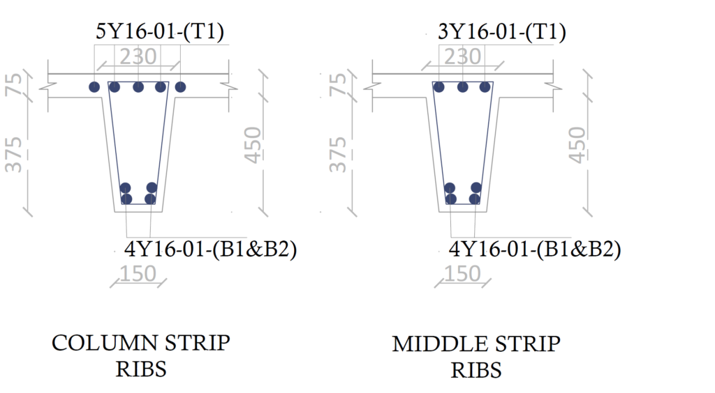
What is worth stating, however is that, whereas a flat slab section is rectangular, the ribs in a waffle slab forms a T-section with the slab toppings, hence at the span the section will be taken as flanged, while at the solid heads (supports) the section can be taken as rectangular. This can have a significance on the quantity of flexural and shear reinforcement provided in the slab as would be seen in the worked example.
Worked Example
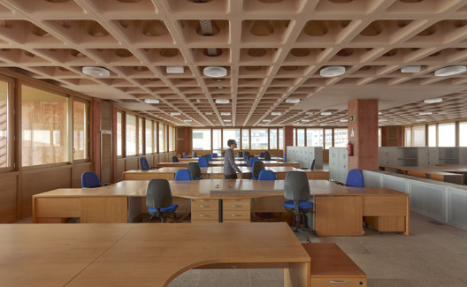
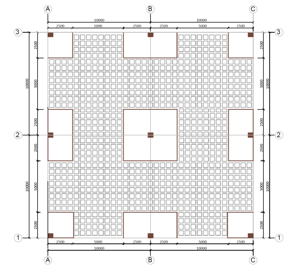
Figure 3 & 4 shows the plan and section of a waffle floor over a school library. Using the data provided in Table 1, carry out sufficient number of calculations to establish the type and quantity of reinforcement required in the slab. Preliminary sizing of the slab has already been completed and is presented as part of the data provided in Table 1.
| Columns (mm) | 450 x 450 |
| Floor depth (mm) | 450 |
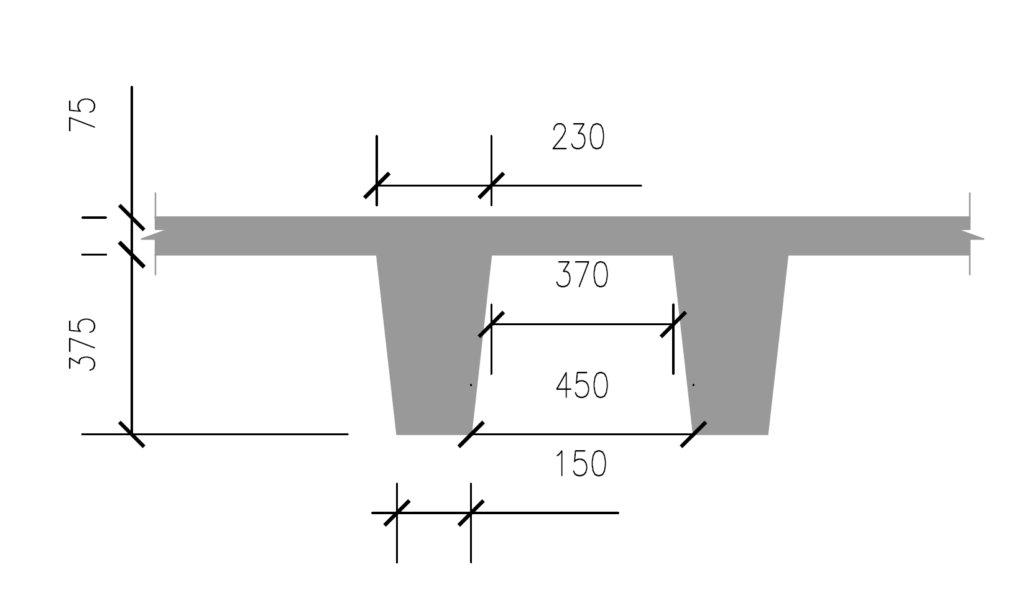
| Ribs (mm) | 150 x 450 @ 600 c/c |
| Concrete | C20/25 |
| Reinforcement | 410Mpa |
| Floor usage | Category C – Congregation |
Actions
Permanent Actions
1) Self weight: The self-weight can be estimated using the same equation as utilized for the waffle slab with banded beams. It is conservative.
{ f}_{ s } =\frac { 25 }{ yz } \left\{ yzh-n\left[ \frac { s }{ 3 } \left( { a }^{ 2 }+{ b }^{ 2 }+\sqrt { { a }^{ 2 }{ b }^{ 2 } } \right) \right] \right\} =\frac { 25 }{ 10\times 10 } \left( 10\times 10\times 0.45-(6\times 32) \right) \times \\ \left( \frac { 0.375 }{ 3 } \left( { 0.45 }^{ 2 }+{ 0.37 }^{ 2 } \right) +\sqrt { 0.45^20.37^2 } \right)\\= 8.2kN/m^22) Finishes
finsihes \quad =1.5kN/m^2
g_k=8.2+1.5 =9.7kN/m^2
Variable Actions
1) Floor Imposed Action
Since floor is to be used for a library a floor-imposed load of 4kN/m2 corresponding to category C within UK NA to BS EN 1991-1-1 will be applied
Imposed\quad action = 3.0kN/m^2
2) Demountable Partitions: Allow for an additional load of 1kN/m2 for movable/demountable partitions on the slab.
partitions =1.0kN/m^2
q_k=3+1.0 =4.0kN/m^2
Design Value of Actions
By inspection the permanent actions are less than 4.5 times the variable actions, therefore equation 6.10b of BS EN 1991-1-1 can be used.
{ n }_{ s }=1.35\xi { g }_{ k }+1.5{ q }_{ k }=(1.35\times 0.925\times 9.7)+(1.5\times 4)\\=18.1{ kN }/{ m }^{ 2 }Analysis
In the design of flat slabs there are several methods that can be used for analysis, including the use of simplified coefficients, equivalent frame methods, yield analysis and finite element analysis. The simplified coefficient method is conservative and always come out handy. However, to use it is contingent upon certain conditions which must be investigated and found to be satisfactory (See Annex I of BS EN 1992-1-1). By inspection, the simplified coefficient method can be applied to analyze this slab.
As with flat slabs, the waffle will be sub-divided into column and middle strips. In the case of a waffle slabs, the column strip would consist of all the ribs connecting to the solid head while the middle strips are those located between the column strips.
Utilizing the coefficient for bending moment and shear force for flat slabs, we have:
Negative Moments @ Supports
M_{sup}=-0.086FLM_{sup}=-0.086\times(18.1\times 10)\times 10^2\\=-1557kN.mPositive Moments @ Spans
M_{span}=0.086FLM_{sup}=0.086\times(18.1\times 10)\times 10^2\\=1557kN.mShear @ Interior Supports
V =0.5F
V=0.5\times(18.1\times10)\times 10 = 905kN
Flexural Design
Before proceeding with the flexural design, the bending moment must be apportioned between the column and middle strips. The negative moment at supports will be shared in the proportion of 60% to the column strip and 40% to the middle strip while the positive moment in the spans will be shared in the proportion of 50-50%.
Assuming 16mm bars in both directions and concrete cover of 25mm, we can determine the mean effective depth for design as:
{ d }_{ y }=h-(c+\phi /2)\\=450-(25+16/2+8)=409mm
{ d }_{ z }=h-(c+\phi /2+\Phi )\\=450-(25+16/2+16+8)=393mm{ d }_{ min }=\frac { { d }_{ y }+{ d }_{ z } }{ 2 } =\frac { 409+393 }{ 2 } =401mmNegative Moment @ Supports
Here, the moment is first shared between the column and middle strip, and then further shared between the ribs.
M= 1557kN.m
Negative moment in column strip
M_{cstrip}=0.6\times \frac { 1557 }{ 5.0 } =186.8kN.m/mNegative moment in ribs in column strip
{ M }_{ Ed }=186.8\times 0.6 = 112kN.m/ribk=\frac { { M }_{ Ed } }{ b{ d }^{ 2 }{ f }_{ ck } } =\frac { 112\times { 10 }^{ 6 } }{ { 600}\times { 401 }^{ 2 }\times 20 } =0.058z=0.95d=0.95\times 401=381mm
{ A }_{ s }=\frac { { M }_{ Ed } }{ 0.87{ f }_{ yk }z } =\frac { 112\times { 10 }^{ 6 } }{ 0.87\times 410\times 381 } \\=824.1{ mm }^{ 2 }/mUse 5T16mm bars -Top (As, prov = 1005mm2)-distributed across flange
Negative moment in middle strips
M_{mid,strip}=0.4\times \frac { 1557 }{ 5.0 } =124.6kN.m/mNegative moment in ribs
{ M }_{ Ed }=124.6\times 0.6 = 74.8kN.m/ribk=\frac { { M }_{ Ed } }{ b{ d }^{ 2 }{ f }_{ ck } } =\frac { 74.8\times { 10 }^{ 6 } }{ { 600}\times { 401 }^{ 2 }\times 20 } =0.039z=0.95d=0.95\times 401=381mm
{ A }_{ s }=\frac { { M }_{ Ed } }{ 0.87{ f }_{ yk }z } =\frac { 74.8\times { 10 }^{ 6 } }{ 0.87\times 410\times 381 } \\=550.4{ mm }^{ 2 }/ribUse 3T16mm bars -Top (As, prov = 603mm2)
Positive Moment in Spans
M= 1557kN.m
Positive moment in column strip
M_{cstrip}=0.5\times \frac { 1557 }{ 5.0 } =155.7kN.m/mPositive moment in ribs in column strip
{ M }_{ Ed }=155.7\times 0.6 = 93.4kN.m/ribk=\frac { { M }_{ Ed } }{ b{ d }^{ 2 }{ f }_{ ck } } =\frac { 93.4\times { 10 }^{ 6 } }{ { 600}\times { 401 }^{ 2 }\times 20 } =0.048z=0.95d=0.95\times 401=381mm
{ A }_{ s }=\frac { { M }_{ Ed } }{ 0.87{ f }_{ yk }z } =\frac { 93.4\times { 10 }^{ 6 } }{ 0.87\times 410\times 381 } \\=687.3{ mm }^{ 2 }/mUse 4T16mm bars -Bottom (As, prov = 804mm2) in two layers
Positive moment in middle strips
M_{mid,strip}=0.5\times \frac { 1557 }{ 5.0 } =155.7kN.m/mPositive moment in ribs in middle strip
{ M }_{ Ed }=155.7\times 0.6 = 93.4kN.m/ribk=\frac { { M }_{ Ed } }{ b{ d }^{ 2 }{ f }_{ ck } } =\frac { 93.4\times { 10 }^{ 6 } }{ { 600}\times { 401 }^{ 2 }\times 20 } =0.048z=0.95d=0.95\times 401=381mm
{ A }_{ s }=\frac { { M }_{ Ed } }{ 0.87{ f }_{ yk }z } =\frac { 93.4\times { 10 }^{ 6 } }{ 0.87\times 410\times 381 } \\=687.3{ mm }^{ 2 }/ribUse 4T16mm bars -Bottom (As, prov = 804mm2) in two layers
Deflection Verification
Waffle slabs are mostly utilized for long spans, it is therefore a no brainer that deflection could be critical. Deflection is verified as done for any concrete element- by comparing the limiting and actual span-effective depth ratios.
{ \left[ \frac { l }{ d } \right] }_{ limit }\ge{ \left[ \frac { l }{ d } \right] }_{ actual }Limiting L/d Ratio
{ \left[ \frac { l }{ d } \right] }_{ limit }=N\cdot k\cdot F1\cdot F2\cdot F3\rho =\frac { { A }_{ s,req } }{ bd } =\frac { 687.3 }{ 600\times 401 } =0.0028{ \rho }_{ o }={ 10 }^{ -3 }\sqrt { { f }_{ ck } } ={ 10 }^{ -3 }\times \sqrt { 20 } =0.00447
N=11+\frac { 1.5\sqrt { { f }_{ ck } } { \rho }_{ o } }{ \rho } +3.2\sqrt { { f }_{ ck } } \left( \frac { { \rho }_{ o } }{ \rho } -1 \right) ^{ \frac { 3 }{ 2 } } N= 19.8
F1=1.0;\quad k=1.5;\quad \\F2=1.0=7/10=0.7
F3=\frac { 310 }{ { \sigma }_{ S } } \le 1.5{ \sigma }_{ S }=\frac { { f }_{ yk } }{ { \gamma }_{ s } } \left[ \frac { { g }_{ k }+{ \psi q }_{ k } }{ { n }_{ s,max } } \right] \left( \frac { { A }_{ s,req } }{ { A }_{ s,pro } } \right) \cdot \frac { 1 }{ \delta }=\frac { 410 }{ 1.15 } \left[ \frac { 8.2+(0.6\times 4) }{ 18.1 } \right] \frac { 687.3 }{ 804} \\=178.4MpaF3=\frac { 310 }{ 178.5 } =1.73\le1.5{ \left[ \frac { l }{ d } \right] }_{ limit }=19.8\times 1.5\times 1\times 0.7\times 1.5\\ =31.2Actual L/d Ratio
{ \left[ \frac { l }{ d } \right] }_{ actual }=\frac { 10000 }{ 401} =24.9Since actual L/d ratio is less than the limiting L/d ratio the requirement with respect to deflection is satisfied.
Shear Design
Here, the maximum shear force will be distributed amongst the ribs. Therefore:
Shear Force/ Rib
V_{Ed} = \frac{905}{5.0}\times0.6 = 108.6kNBy inspection, shear reinforcement is required in the ribs.
\theta =0.5{ sin }^{ -1 }\left( \frac { { 5.56V }_{ Ed } }{ { b }_{ w }d\left( 1-{ f }_{ ck }/250 \right) { f }_{ ck } } \right)\theta =0.5{ sin }^{ -1 }\left( \frac { 5.56\times 108.6\times { 10 }^{ 3 } }{ 150\times 401\left( 1-20/250 \right) 20 } \right) \\=16.5^{ \circ }cot\theta =3.33>2.5\quad therefore\quad cot\theta =2.5
\quad z=0.9d=0.9\times 401=361mm
\frac { { A }_{ sv } }{ { s }_{ v } } \ge \frac { { V }_{ Ed } }{ z{ f }_{ ywd }cot\theta } =\frac { 108.6\times { 10 }^{ 3 } }{ 401\times 410\times 2.5 } \\=0.26 { s }_{ v }=0.75d=0.75\times 486\\=364.5mmUse T8mm bars @ 300mm Centers Bottom (As, prov/sv =0.34)
Punching Shear Design
To conclude this design, the possibility of the column punching through the slab at the solid head must be verified. But since most waffle slabs with solid head are generally deeper than traditional flat slabs, it follows that punching shear may not be too critical, hence it is ignored in this article. However, as a good design practice, punching shear verification should be carried out.
See: Designing for Punching Shear in Concrete Slabs
Design Resume
Provide Mesh A142 in top of slab toppings to prevent cracking.