This article relates to the design of moment resisting column bases – a type of column base plate that must transmit bending moment in addition to axial and shear forces to the foundation.
Column base plates are provided beneath steel columns in order to transmit the applied design forces safely to the foundations. Steel columns are heavily loaded, and their cross-sections are typically small. Applying these loads directly on the foundation could possibly result in a shear or punching failure. Hence, it is the practice to provide a steel plate beneath the column in order to spread the column load over a large base area.
A vast majority of column base plate encountered in practice are typically constructed in simple connections since braced frames is favoured for muti-Storey steel buildings. However, there are scenarios where connections can no longer be simple, and there must be some transmission of bending moment. Such as where a steel column is to support a heavily loaded cantilever, in some portal frames and ultimately in moment frames, where connections are actually allowed to transmit significant bending moments.
This article relates to the design of column base plates that must transmit bending moment in addition to axial and shear forces to the foundation. The principles and procedures presented for design are in accordance with the current BS EN 1993-1-18.
Detailing a Moment-Resisting Base Plate
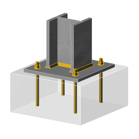
In detailing a moment resisting base plate, exactly all the rules observed in detailing a simple or pinned based plate is also valid. Typically, the base plate consists of a single plate, fillet welded to a steel column and then attached to the foundation with hold-down bolts. The bolts are normally cast into the foundations with anchor plates to avoid pull out. High strength grout is also poured in between the interface of the base plate and foundation (Figure 1).
The base plates are usually cut from S275 or S355 steel. Fillet welds of 8mm or 10mm are typically provided along the side of the flanges and a short distance either side of the web. The
Recommended Layout
As stated for pinned bases, moment resisting bases must also be detailed based on the following considerations:
- The plate size must be of sufficient size to spread the loads from the column to the foundation and accommodate the anchor bolts.
- The setting out dimensions for the anchor bolts should be on a regular and simple geometry.
- The base plate and holding down system should be sufficiently robust to withstand loads experienced during construction. E.g. from wind, non-verticality etc.
Designing a Moment-Resisting Base Plate
The design model for analyzing the combined axial force and bending moment at the base of a steel column is covered by BS-EN-1993-1-8. The basic assumption here is that the resistance to the forces must be provided by two T-stubs in the base plate. Of the two T-stubs, one is in compression and the other is in tension. For the one in tension, resistance will be provided by the holding down bolts outside the flange of the steel columns. While for the one in compression, resistance is being provided by a compression zone in the concrete, concentric with the column flange.
Three situations can be imagined based on this model. First, where the bending moment is small or large relative to the axial force. Or secondly, where the moment is significantly small such that there is no net tension and therefore there is no account taken of the compression resistance under the web. Thirdly, where the moment is significantly large such that it ignores the possibility of a greater moment of resistance due to a compression zone that is outside the flange of the column. Out of the three situations, the first scenario covers a vast majority of the situations that will be typically encountered in practice and incidentally, it is the only situation covered by BS EN 1993-1-8.
In designing the base, the approach requires a trial base plate geometry and bolt configuration is selected, the geometry and configuration are then verified for the range of resistances to the applied combined axial forces and bending moments. The procedure can be summarized into the following steps.
- Determine the forces in the equivalent T stubs for both flanges. For flanges in compression the forces may be assumed to be concentric with the flange. For a flange in tension, the force is assumed to be along the line of the holding down bolt.
- Determine the design resistances of the equivalent T-stub in compression.
- Determine the design resistances of the equivalent T-stub in tension.
- Verify the adequacy of the base plate connection to shear
- Verify the adequacy of the welds in the connection
These steps are expatiated in the subsequent sub-sections.
Step 1: Determining the Forces in the T-Stubs
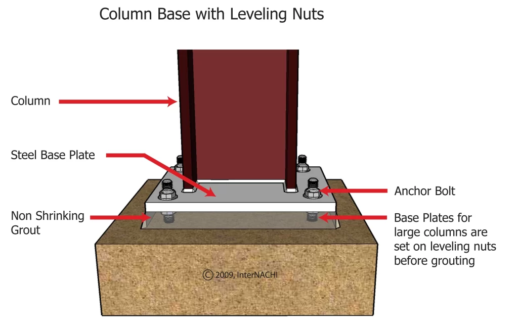
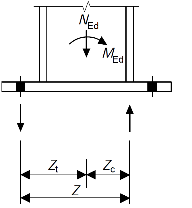
This typically involves evaluating the forces in the T-Stubs. This is done by considering the position of the reactions with respect to the centerlines of the column (Figure 1). Tensile resistance is at a distance zt from the column centerlines on either side, while compressive resistance is at a distance zc from the centerline of the column on either side.
To determine the forces in the T-stub, we must first determine the forces in the column flanges. These is given as:
N_{L,f} =\frac{N_{Ed}}{2}-\frac{M_{Ed}}{h-t_{f}}N_{R,f} =\frac{N_{Ed}}{2}+\frac{M_{Ed}}{h-t_{f}}Where the NL,f and NR,f are the forces in the left and right flanges. The values of NL,f and NR,f will indicate which flange is in compression and tension. A positive value of N indicates compression while a negative value indicates tension.
The forces in the T-stubs are then given as:
N_{L,f} =\frac{N_{Ed} \times z_R}{(z_L +z_R)}-\frac{M_{Ed}}{(z_L +z_R)}N_{L,f} =\frac{N_{Ed} \times z_R}{(z_L +z_R)}+\frac{M_{Ed}}{(z_L +z_R)}Where zL and zR corresponds to either zc or zt depending on whether the flange on that side (left or right) is in tension or compression.
Step 2: Evaluate the Resistance of the Compression T-Stub
Having determined the forces in the T-stub, the next step is to evaluate the resistance of the T-stub in compression.
The resistance of the T-stub in compression is the lesser of:
- The resistance of the foundation in bearing
- The resistance of the base plate in bending
Resistance of Foundation in Bearing
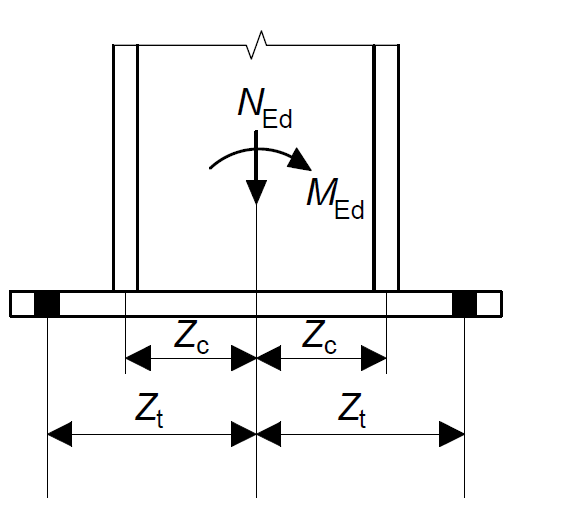
The resistance of the foundation in bearing depends on the effective area resulting from the dispersal of the compression force by the base plate in bending (Figure 3).
The design compression resistance for most typical foundation is given as:
F_{C,Rd}=0.85 \frac{f_{ck}}\gamma_{c}b_{eff}l_{eff}Where: fck is the characteristics compressive strength of the concrete and γc is the material factor of safety of concrete Leff and beff are as shown in figure 3. c in figure 3 is the additional bearing width given as:
c = t_{bp} \sqrt \frac{f_{y,yp}}{3f_{jd}\gamma_{M0}}Resistance of Base Plate in Bending
The compression resistance of the column flange and web in the compression zone is given as
F_{c,fc,Rd}=\frac{M_{c,Rd}}{h_{c}-t_{fc}}Step 3: Evaluate the Resistance of the Tension T-Stub
The resistance of the tension T stub is the smaller of:
- The resistance of the base plate in bending
- The resistance of the holding down bolts
- The resistance of the column flange and web in tension
Resistance of Base Plate in Bending
The resistance of the base plate in bending is given as:
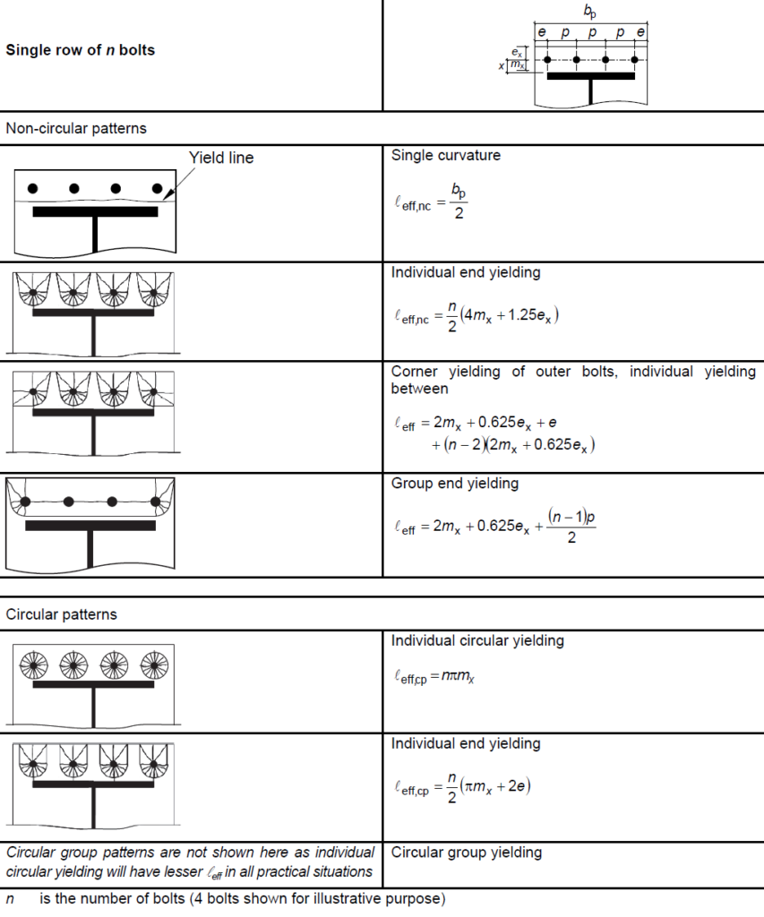
F_{t,pl,Rd}=\frac{0.5 Σl_{eff,1}t^2_{pl}f_y}{m_x\gamma_{M0}}where: leff,1 is the effective length of the equivalent T stub (determined from Figure 4); tpl is the thickness of the base plate; fy is the yield strength of the base plate; mx is the distance from the bolt centerline to the fillet weld to the column flange (measured to a distance into the fillet equal to 20% of its size).
Resistance of Bolts in Tension
The design resistance of a single bolt group is given as:
F_{t,pl,Rd}=nF_{t,Rd}Where: n is the number of bolts and Ft,Rd is the design resistance of a single bolt group.
Step 4: Verify the Adequacy of the Base Plate to Shear
There are several ways by which shear may be resisted in a base plate connection. The simplest of them all is to assume that the shear force is being resisted by friction between the base plate itself and its foundation. When friction alone is insufficient, the next approach is to assume that the holding down bolts will also assist in resisting shear, since they are typically cast into concrete. Hence, it has been the practice to omit this check in the design of base plates. However, the designer as to be weary of certain arrangement may cause a base plate to be subjected to a ‘high shear.’
This is article covers only the base plates that would be typically encountered in practice, hence the verification of moment resisting base plate to high shear is not covered. However, insights on how and when to evaluate moment resisting base plate for high shear may be obtained from the texts in the sources and citation section of this article.
Step 5: Verify the Adequacy of the Welds
The objective of verifying the adequacy of the welds in the base plate connection is to ensure that the anchorage they provide are as strong as the bolts used. The basic requirement is as follows:
V_{Rd,cs} \ge V_{Ed}Where: VEd is the design shear force in the bolts taken as the total tension force in the bolts been considered within the control perimeter and VRd,cs is the resistance to punching shear in accordance with BS EN 1992-1 (See: Design for Punching Shear in Concrete Slabs)
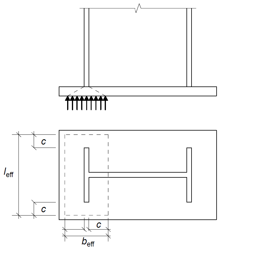
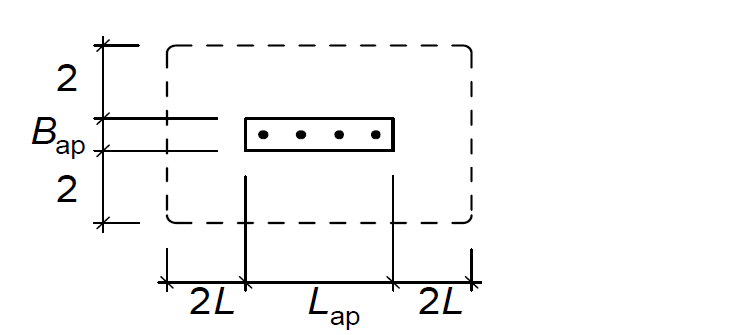
Here, the basic control perimeter is determined at a distance outside of the loaded area that is twice the effective depth of the slab. For a column base, the effective length is taken as the length of the anchor bolts. If the bolts are placed such that their basic control perimeter overlap as would mostly be the case in moment resisting frame, then they should be checked as a group with a single control perimeter (Figure 5)
See: Simple Connections in Multi-Storey Buildings
Worked Example
A 305 × 305 × 118 UKC column in a Multi-Storey steel building carries a design axial action of 2200kN and bending moment of 300kN.m along the major axis. Design a base plate for this column in grade S275 steel. Assuming the base plate sits on a pile cap made from class C40/50 concrete.
Geometrical Properties
Depth hc =314.5mm; Width bc = 307.4mm; flange thickness; tf,c = 18.7mm; web thickness; tw,c = 12.0mm; Wel,y,c = 1760000mm3; Wpl,y,c = 1960000mm3; Area of section A = 15000mm2
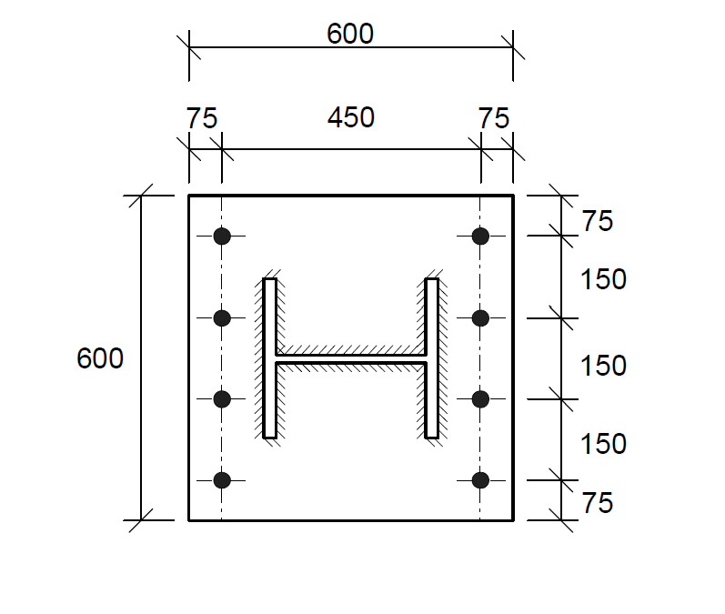
Try a base plate of (600× 600× 50mm) and 8Nos of M24 8.8 bolts. The trial layouts as shown in the Figure 5 below:
Material Properties
Steel
For S 275 Steel and 16 < tf,c < 40
- Base plate yield strength = fy,c = ReH = 255N/mm2
- Base plate ultimate strength fu,tp = Rm = 410N/mm2
Concrete
For C40/50 Concrete
- Characteristics strength of concrete fck = 40Mpa
Bolts
For class 8.8 bolts
- Nominal yield strength fyb = 640N/mm2
- Nominal ultimate strength fub = 800N/mm2
Step 1: Determine the Forces at the Column Base and in the T-Stub
As already stated in the article, the design moment of resistance of the base depends on the resistances of the two T-Stubs, one for each flange of the columns. It must be determined whether they are in tension and compression. Weather each of them is in tension or compression will depend on the magnitude of the applied axial forces and bending moments.
Forces in the flanges due to axial forces and bending moments:
N_{L,f} =\frac{N_{Ed}}{2}-\frac{M_{Ed}}{h-t_{f}} =\frac{2200}{2}-\frac{300}{314.5-18.7}= -86kNN_{R,f} =\frac{N_{Ed}}{2}+\frac{M_{Ed}}{h-t_{f}} =\frac{2200}{2}+\frac{300}{314.5-18.7}= 2114kNTherefore, the left column flange is in tension while the right flange is in compression. The resistance of the two T-stubs must therefore be centered along the lines.
Recall the assumption from our design model, tension will be resisted on the of the bolts and compression resisted concentrically under the flange in compression. Following this assumption, the corresponding lever arms can be calculated from figure 7 as follows:
Z_t = 450/2 = 225mm
Z_c = \frac{(314.5 -(18.7)}{2}=148mmTherefore, the forces in the T-stubs can be evaluated as
N_{L,T} =\frac{N_{Ed} \times z_R}{(z_L +z_R)}+\frac{M_{Ed}}{(z_L +z_R)}=-\frac{2000 \times 148}{(225 +148)}+\frac{300}{(225 +148)} \\= 10.7kNN_{R,T} =\frac{N_{Ed} \times z_R}{(z_L +z_R)}-\frac{M_{Ed}}{(z_L +z_R)}=-\frac{2000 \times 148}{(225 +148)}-\frac{300}{(225 +148)} \\= -1597.9kNStep 2: Resistance of Compression T-Stub
The next step is to evaluate the resistance of the T-Stubs. First, we will evaluate the resistance of the compression T-Stub
Recall that the resistance of the compression T stub is the lesser of the resistance of the foundation in bearing and resistance of the plate in bending ( Fc,pl,Rd and Fc,cf,Rd).
Resistance of Foundation in Bearing
To determine the magnitude of the resistance to bending, we must determine the length and breadth of the bearing area. However, we must first determine the additional bearing width c which depends on the plate thickness, plate strength and joint strength.
c = t_{bp} \sqrt \frac{f_{y,yp}}{3f_{jd}\gamma_{M0}} = 50\sqrt \frac{255}{3\times 17 \times1.0} \\=112mmHaving computed the value of c, the length and width of the bearing area is computed as follows:
b_{eff} = 2c +t_{fc} =2\times 112 +18.7 \\=243mml_{eff} = 2c +b_{c} =2\times 112 +307.4 \\=531mmThus, the resistance of the foundation is:
F_{C,Rd}=0.85 \frac{f_{ck}}\gamma_{c}b_{eff}l_{eff} =0.85\times \frac{40}{1.5}\times 243\times531=2924.8kN
Resistance of Plate to Bending
By inspection the shear can be neglected, hence this can be evaluated using the following. equation:
F_{c,fc,Rd}=\frac{M_{c,Rd}}{h_{c}-t_{fc}} = =\frac{345\times 1960000/1.0}{314.5-18.7} =2286kN
Since Fc,pl,Rd > Fc,cf,Rd therefore the compression resistance of the right-hand T – Stub is Fc,cf,Rd = 2286kN. And in any case Fc,cf,Rd > NRT = 1597.9kN (o.k)
Step 3: Resistance of Tension T-Stub
The resistance of the T-stub in tension is the lesser of the base plate in bending under the left column flange and the column flange/web in tension. To evaluate we must evaluate the resistance of the base plate in bending which is given as:
F_{t,pl,Rd} = F_{T,Rd} = min [ F_{T,1-2,Rd} ; F_{T,3,Rd}FT,1-2,Rd deals with the resistance of the plate in bending, but before we can determine its magnitude, we must first determine the effective length of the T stub, which is determined based on the table in Figure 4. In many instance the length of the T-stub can be determine by inspection, in order to select the possible yield line that would produce the minimum values considering the circular and non-circular patterns. For this example:
l_{eff,1} =0.5b_{bp} =0.5\times 600 =300mmThus, resistance of the plate to bending:
F_{T,1-2,Rd} =\frac{0.5 Σl_{eff,1}t^2_{pl}f_y}{m_x\gamma_{M0}}=\frac{0.5\times 300 \times 50^2 \times 255}{60\times 1.0}= 1594kNResistance of the bolts in tension assuming 4 rows of 8.8 M24 bolts (Ft,Rd)= 203kN):
F_{T,3,Rd}=nF_{t,Rd} = 4\times203 =812kNSince FT,1-2,Rd > FT,3,Rd therefore the tensile resistance of the T – Stub is FT,3,Rd = 812kN. And in any case Fc,cf,Rd > NRT = 10.7kN (o.k)
Step 5: Verify the Adequacy of the Shear & Welds
As explained the verification for shear can often be ignored in most instances therefore this check is not carried out here. Also, by inspection, the verification of the welds is not critical and would therefore be ignored since the maximum tensile force is significantly less than the resistance of the flange, hence full-strength welds are not required.
Design Summary
Provide a 600 × 600 × 50mm moment resisting base plate with 8 Nos of M24 property class 8.8 bolts and 10mm fillet welds.
Sources & Citations
- BS EN 1993-1-8: 2005 Eurocode 3: Design of Steel Structures. Part 1-8: Design of Joints, BSI 2010.
- NA to BS EN 1993-1-8: 2005 U.K National Annex to Eurocode 3 Design of Steel Structures. Part 1-8: Design of Joints, BSI 2008.
- Joints in Steel Construction: Moment-Resisting Joints to Eurocode 3. (SCI – P398), SCI, 2013.