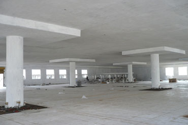
Flat slabs are reinforced concrete slabs supported directly on columns, without beams. They are sometimes thickened at the columns to form column drops. These drops are very effective when the negative moments at supports are quite high or where punching stresses are very critical and punching reinforcement is not desired. It is also not unusual to increase the size of columns at the slab-column interface to produce a column head. Column heads can reduce the effective span of the slab, hence, the internal forces and deflection are reduced.
The benefits of a flat slab over other slab types are numerous: They are suitable for irregular column layout. The absence of drop beams means that their formwork is simplified, thus increasing the pace of construction. They also offer reduced storey heights, level soffits, flexible arrangement and distribution of services est.
Analysis and Design
Analysis of Flat Slabs
There are several methods available for analyzing a flat slab. This includes the use of simplified coefficients, equivalent frame method, yield line analysis, grillage analysis and the finite element method. The use of simplified coefficients is subject to certain conditions (please see Annex I of BS EN 1992-1- 1). The yield line and finite element methods are particularly more suited for computer programs. Hence, this post will focus only on the equivalent frame method of analyzing flat slabs.
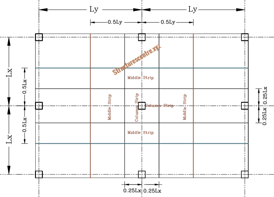
In the equivalent frame method, we divide the slab in the two orthogonal directions into frames consisting of column strips and middle strips as shown in figure 1. The vertical load on the frame is taken based on the width between the centrelines of panels. Each of this frame will be divided into a series of subframes, consisting of the slab at one level and the columns above and below it.
In analyzing the subframes, the stiffness’s of edge columns are usually multiplied by 0.7. This is because the equivalent frame method overestimates the restraints provided by edge and corner columns. This is based on a research conducted by the concrete society on flat slabs.
Analysis of subframes have been presented in a previous post, therefore, in this post, only the bending moment diagrams might be presented.
Transfer Moments
The maximum moment, that can be transferred to an edge or corner column is given as:
{ M }_{ t,max }=0.17{ b }_{ e }{ d }^{ 2 }{ f }_{ ck }
Where:
- be s the effective width of the flat slab (see figure 2)
- d is the effective depth of the top reinforcement in the column strip
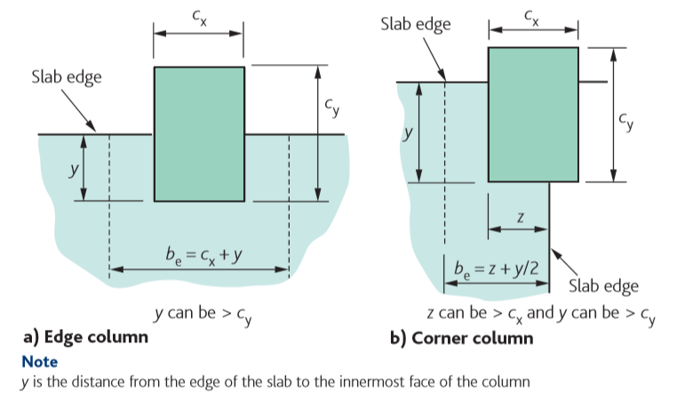
Where the moment at an end support exceeds the maximum transfer moment, moment redistribution must then be carried out.
Design of Flat Slabs
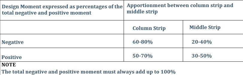
Haven determined the moments. The positive moment in the spans, as well as the negative moment at supports will be divided into a column and a middle strip, see figure 1. The moment is then apportioned to the column and middle strip using table 1.
Once the moment has been determined, the design will proceed in a similar fashion for concrete slabs. The critical areas include flexural design, punching shear and deflection.
An additional requirement in flat slabs is to place at least 50% of the hogging reinforcement over the middle quatre of the column strip.
Worked Example
Figure 3 shows the layout of a shopping mall building. The floors are required to have level soffits, hence drops and column heads are not permitted. All columns are 400mm2 and the floor-floor distance =4m. The slab is expected to be constructed from C20/25 concrete and concrete steel bars having a yield strength of 410Mpa.
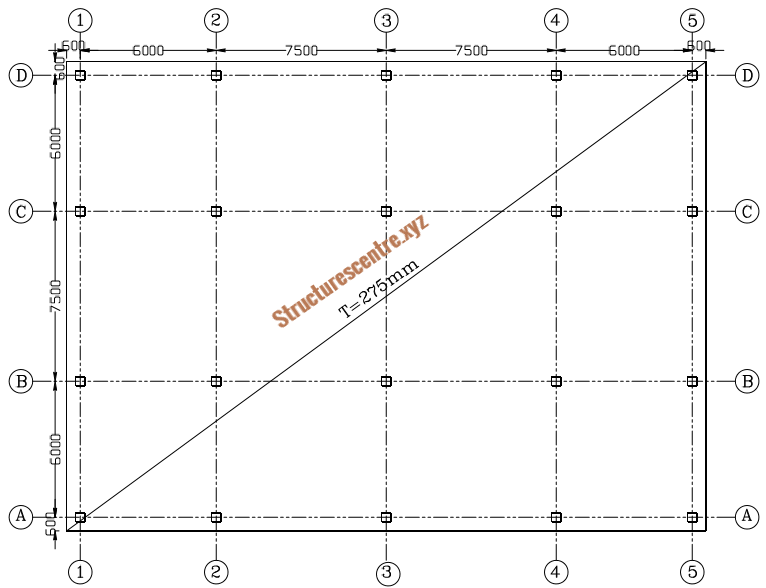
Designing the whole slab will make this post unnecessarily long. Therefore to illustrate the process only sub-frame 3-3 will be designed. You can complete the design in your free time to gain confidence.
Actions
Note that the slab thickness has been sized conservatively i.e. 275mm thick. Guidance on sizing a flat slab can be obtained from the concrete centre publication: Economic Concrete Frame Elements.
Permanent Actions
a.\quad self\quad weight\quad of\quad slab\quad \\=0.275\times 25=6.875kN/{ m }^{ 2 }
b.\quad finishes\quad \& \quad services\quad =1.5kN/{ m }^{ 2 }
Permanent\quad Actions\quad { g }_{ k }=6.875+1.5\\=8.375kN/{ m }^{ 2 }
Variable Actions
a.\quad Imposed\quad Load\quad (shopping\quad mall)\\=4kN/{ m }^{ 2 }
b.\quad movable\quad partitions\quad =1kN/{ m }^{ 2 }
{ Variable\quad Actions\quad q }_{ k }=4+1=5kN/{ m }^{ 2 }
Design Values of Actions
By inspection the permanent actions are less than 4.5 times the variable actions, therefore equation 6.10b of BS-EN 1991-1-1 can be used.
{ n }_{ s,max }=1.35\xi { g }_{ k }+1.5{ q }_{ k }
=(1.35\times 0.925\times 8.375)+(1.5\times 5)\\=17.96kN/{ m }^{ 2 }
{ n }_{ s,min }=1.35\xi { g }_{ k }
=(1.35\times 0.925\times 8.375)=10.46kN/{ m }^{ 2 }
Analysis of Sub-Frame 3
Analysis of Sub-frames have been presented in a previous post, therefore only bending moment diagram will be shown here. If you would like to review it click: How to Analyse Elements in Braced Frames

Load transferred to subframe 3
tributary\quad width\quad =\frac { 7.5 }{ 2 } +\frac { 7.5 }{ 2 } =7.5m
{ w }_{ max }={ n }_{ s,max }\cdot width=17.96\times 7.5\\=134.7kN/m
{ w }_{ min }={ n }_{ s,max }\cdot width=10.46\times 7.5\\=78.45kN/m
Analysis of this subframe will be carried out for three loadcases:
- All spans loaded with the maximum actions, wmax
- Alternate spans loaded with the maximum actions while the other spans are loaded with the minimum actions.
The analysis will then be carried out by moment distribution. Limited moment redistribution of the support moment into the spans can be carried out if need be.

Flexural Design
The moment is apportioned between the column and middle strips within the specified limits in table 1. For this frame, the negative moment at supports will be shared in the proportion of 70% to the column strip and 30% to the middle strip while the positive moment in the spans will be shared in the proportion of 50-50%.
Assuming 16mm bars in both direction and a concrete cover of 25mm
{ d }_{ y }=h-(c+\phi /2)\\=275-(25+16/2)=242mm
{ d }_{ z }=h-(c+\phi /2+\Phi )\\=275-(25+16/2+16)=226mm
{ d }_{ min }=\frac { { d }_{ y }+{ d }_{ z } }{ 2 } =\frac { 242+226 }{ 2 } =234mm
End Supports
The width of the end support, be=cx +y =(600+200)+400=1200mm
{ M }_{ t,max }=0.17{ b }_{ e }{ d }^{ 2 }{ f }_{ ck }
=0.17\times 1200\times { 234 }^{ 2 }\times 20=223.4kN.m
{ M }_{ Ed }=159kN.m(<223.4kN.m)
k=\frac { { M }_{ Ed } }{ b{ d }^{ 2 }{ f }_{ ck } } =\frac { 159\times { 10 }^{ 6 } }{ 1200\times { 234 }^{ 2 }\times 20 } =0.121
z=d\left[ 0.5+\sqrt { 0.25-0.882k } \right] \le 0.95d
=0.88d=0.88\times 234=205.92mm
{ A }_{ s }=\frac { { M }_{ Ed } }{ 0.87{ f }_{ yk }z } =\frac { 159\times { 10 }^{ 6 } }{ 0.87\times 410\times 205.92 } \\=2164.7{ mm }^{ 2 }2
Try\quad 12Y16\quad @\quad 100mm\quad centres\quad\\ ({ A }_{ s,prov }=2412{ mm }^{ 2 })
End Spans
width\quad of\quad column\quad strip\quad \\=\frac { 6000 }{ 4 } \times 2=3000m
width\quad of\quad middle\quad strip\quad\\ =7500-3000=4500mm
M=313kN.m
Column Strip
{ M }_{ Ed }=0.5\times \frac { 313 }{ 3.0 } =52.17kN.m/m
k=\frac { { M }_{ Ed } }{ b{ d }^{ 2 }{ f }_{ ck } } =\frac { 52.17\times { 10 }^{ 6 } }{ { 10 }^{ 3 }\times { 234 }^{ 2 }\times 20 } =0.048
z=d\left[ 0.5+\sqrt { 0.25-0.882k } \right] \le 0.95d
=0.95d=0.95\times 234=222.3mm
{ A }_{ s }=\frac { { M }_{ Ed } }{ 0.87{ f }_{ yk }z } =\frac { 52.17\times { 10 }^{ 6 } }{ 0.87\times 410\times 222\times .3 } \\=657.92{ mm }^{ 2 }/m
Try\quad 20Y12-150mm\quad centres\quad \\({ A }_{ s,prov }=753{ mm }^{ 2 }/m)
Middle Strip
{ M }_{ Ed }=0.5\times \frac { 313 }{ 4.5 } =34.78kN.m/m
k=\frac { { M }_{ Ed } }{ b{ d }^{ 2 }{ f }_{ ck } } =\frac { 34.78\times { 10 }^{ 6 } }{ { 10 }^{ 3 }\times { 234 }^{ 2 }\times 20 } =0.032
z=d\left[ 0.5+\sqrt { 0.25-0.882k } \right] \le 0.95d
=0.95d=0.95\times 234=222.3mm
{ A }_{ s }=\frac { { M }_{ Ed } }{ 0.87{ f }_{ yk }z } =\frac { 34.78\times { 10 }^{ 6 } }{ 0.87\times 410\times 222.3 } \\=438.62{ mm }^{ 2 }/m
Try\quad 23Y12-200mm\quad centres\quad\\ ({ A }_{ s,prov }=565{ mm }^{ 2 }/m)
Interior Supports
width\quad of\quad column\quad strip\quad =\frac { 7.5 }{ 4 } \times 2\\=3.75m
width\quad of\quad middle\quad strip\quad=7.5-3.75\\=3.75mm
M=602kN.m
Column Strip
{ M }_{ Ed }=0.7\times \frac { 602 }{ 3.75 } =112.37kN.m/m
k=\frac { { M }_{ Ed } }{ b{ d }^{ 2 }{ f }_{ ck } } =\frac { 112.37\times { 10 }^{ 6 } }{ { 10 }^{ 3 }\times { 234 }^{ 2 }\times 20 } =0.103
z=d\left[ 0.5+\sqrt { 0.25-0.882k } \right] \le 0.95d
=0.90d=0.90\times 234=210.6mm
{ A }_{ s }=\frac { { M }_{ Ed } }{ 0.87{ f }_{ yk }z } =\frac { 112.37\times { 10 }^{ 6 } }{ 0.87\times 410\times 222.3 } \\=1495.6{ mm }^{ 2 }/m
Try\quad 30Y16-125mm\quad centres\quad ({ A }_{ s,prov }\\=1608{ mm }^{ 2 }/m)
Middle Strip
{ M }_{ Ed }=0.3\times \frac { 602 }{ 3.75 } =48.16kN.m/m
k=\frac { { M }_{ Ed } }{ b{ d }^{ 2 }{ f }_{ ck } } =\frac { 48.16\times { 10 }^{ 6 } }{ { 10 }^{ 3 }\times { 234 }^{ 2 }\times 20 } =0.044
z=d\left[ 0.5+\sqrt { 0.25-0.882k } \right] \le 0.95d
=0.95d=0.95\times 234=222.3mm
{ A }_{ s }=\frac { { M }_{ Ed } }{ 0.87{ f }_{ yk }z } =\frac { 48.16\times { 10 }^{ 6 } }{ 0.87\times 410\times 222.3 } \\=607.4{ mm }^{ 2 }/m
Try\quad 25Y12-150mm\quad centres\quad ({ A }_{ s,prov }\\=753{ mm }^{ 2 }/m)
Interior Span
width\quad of\quad column\quad strip\quad =\frac { 7.5 }{ 4 } \times 2\\=3.75m
width\quad of\quad middle\quad strip\quad =7.5-3.75\\=3.75mm
M=398kN.m
Column Strip
{ M }_{ Ed }=0.5\times \frac { 398 }{ 3.75 } =53.07kN.m/m
k=\frac { { M }_{ Ed } }{ b{ d }^{ 2 }{ f }_{ ck } } =\frac { 53.07\times { 10 }^{ 6 } }{ { 10 }^{ 3 }\times { 234 }^{ 2 }\times 20 } =0.048
z=d\left[ 0.5+\sqrt { 0.25-0.882k } \right] \le 0.95d
=0.95d=0.95\times 234=222.3mm
{ A }_{ s }=\frac { { M }_{ Ed } }{ 0.87{ f }_{ yk }z } =\frac { 53.07\times { 10 }^{ 6 } }{ 0.87\times 410\times 222.3 } \\=669.28{ mm }^{ 2 }/m
Try\quad 25Y12-150mm\quad centres\quad \\({ A }_{ s,prov }=753{ mm }^{ 2 }/m)
Middle Strip
{ M }_{ Ed }=0.5\times \frac { 398 }{ 3.75 } =53.07kN.m/m
k=\frac { { M }_{ Ed } }{ b{ d }^{ 2 }{ f }_{ ck } } =\frac { 53.07\times { 10 }^{ 6 } }{ { 10 }^{ 3 }\times { 234 }^{ 2 }\times 20 } =0.048
z=d\left[ 0.5+\sqrt { 0.25-0.882k } \right] \le 0.95d
=0.95d=0.95\times 234=222.3mm
{ A }_{ s }=\frac { { M }_{ Ed } }{ 0.87{ f }_{ yk }z } =\frac { 53.07\times { 10 }^{ 6 } }{ 0.87\times 410\times 222.3 } \\=669.28{ mm }^{ 2 }/m
Try\quad 25Y12-150mm\quad centres\quad \\({ A }_{ s,prov }=753{ mm }^{ 2 }/m)
Deflection Verification
The deflection requirement is more critical in the interior span, therefore we can carry out the check this span alone.
Limiting L/d ratio
{ \left[ \frac { l }{ d } \right] }_{ limit }=N\cdot k\cdot F1\cdot F2\cdot F3
\rho =\frac { { A }_{ s,req } }{ bd } =\frac { 669.28 }{ { 10 }^{ 3 }\times 234 } =0.0029
{ \rho }_{ o }={ 10 }^{ -3 }\sqrt { { f }_{ ck } } ={ 10 }^{ -3 }\times \sqrt { 25 } =0.00447
N=11+\frac { 1.5\sqrt { { f }_{ ck } } { \rho }_{ o } }{ \rho } +3.2\sqrt { { f }_{ ck } } \left( \frac { { \rho }_{ o } }{ \rho } -1 \right) ^{ \frac { 3 }{ 2 } }
= 11+\frac { 1.5\times \sqrt { 20 } \times 4.5 }{ 2.9 } +3.2\sqrt { 20 } \left( \frac { 4.5 }{ 2.9 } -1 \right) ^{ \frac { 3 }{ 2 } }
=27.04
F1=1.0;\quad k=1.5;\quad F2=1.0
F3=\frac { 310 }{ { \sigma }_{ S } } \le 1.5
{ \sigma }_{ S }=\frac { { f }_{ yk } }{ { \gamma }_{ s } } \left[ \frac { { g }_{ k }+{ \psi q }_{ k } }{ { n }_{ s,max } } \right] \left( \frac { { A }_{ s,req } }{ { A }_{ s,pro } } \right) \cdot \frac { 1 }{ \delta }
=\frac { 410 }{ 1.15 } \left[ \frac { 8.375+(0.6\times 5) }{ 17.96 } \right] \frac { 669.28 }{ 753 } \times \frac { 1 }{ 0.8 } \\=236.11Mpa
F3=\frac { 310 }{ 236.11 } =1.31
{ \left[ \frac { l }{ d } \right] }_{ limit }=27.04\times 1.5\times 1\times 1\times 1.31\\ =53.2
Actual Deflection
{ \left[ \frac { l }{ d } \right] }_{ actual }=\frac { 7500 }{ 234 } =32.05
Since actual span-effective depth ratio is less than the limiting value, the deflection requirement is okay.
This concludes the design of subframe 3. The frame in the other directions must also be analyzed and designed accordingly.
Punching verification must be carried out and if shear reinforcement is required, it should be provided. This was also the subject of a previous post, see: Designing for Punching Shear in Concrete Slab Other detailing checks must also be carried out before detailing the slab.
Thank You!!!
tadalafil 5 mg mexico – generic tadalafil tadalafil medication cost
viagra sildenafil citrate – cheap viagra 25 viagra buy online
where can i buy cialis online in canada – cialis visa cheap cialis 60 mg
generic stromectol online – ivermectin without a doctor prescription stromectol 15 mg
casino online games for real money – casino online casino no deposit bonus
ed cure – online ed pills medication for ed dysfunction
deltasone 20 mg tablet – prednisone without prescription buy prednisone online fast shipping
how to order cialis from india – Cialis online store online pharmacy pain medicine
ivermectin 9 mg tablet – stromectol uk ivermectin cream canada cost
best otc ed pills – buy ed pills erectile dysfunction medications
ventolin hfa inhaler – gnrventolin.com ventolin nebules
how much is cytotec – where can i buy cytotec pills cytotec for abortion
doxycycline uk – doxycycline 100mg tablet brand name purchase doxycycline online uk
neurontin 300mg caps – canada neurontin 100mg lowest price synthroid prices
Cialis Was Ist Dass
viagra for women pink pill – sildenafil 100 mg tablet coupon where can i get female viagra
cialis price
https://buytadalafshop.com/ – Cialis
cialis rite aid
cialis online legal – cialis prescription discount cialis prescription coupon
propecia generic
who makes vardenafil – vardenafil 120 pills viagra vs cialis vs vardenafil
https://buysildenshop.com/ – Viagra
Doxycycline Hyclate 100mg Tablet
http://buysildenshop.com/ – Viagra
Cialis
ivermectin cream uk – ivermectin 0.5% brand name ivermectin for covid 19
prednisone daily – cheap generic prednisone 50mg prednisone tablet
buy cheap accutane online – accutane generic canada accutane 80 mg daily
levitra vs cialis vs viagra
price of amoxicillin without insurance – amoxicillin for sale for humans buy amoxicillina 500 mg from mexico
Pfizer Website Viagra Sales
buying an essay – buy cheap essay academicwriting
http://buytadalafshop.com/ – order cialis
https://buypropeciaon.com/ – Propecia
viagra 150mg online – Buy branded viagra buy discount viagra
http://buystromectolon.com/ – Stromectol
Stromectol
best australian online pharmacy – Buy cialis generic wholesale pharmacy
ivermectin tablets uk – buy stromectol canada ivermectin canada
cialis chez les jeunes
1 mg prednisone daily – prednisone online prednisone 30g