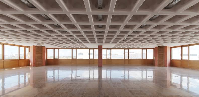
Waffle slabs are not different from a ribbed slab, their design is indeed based on the same principle as the ribbed and troughed slab system. The only difference is that waffle slabs have ribs spanning both directions and as a result, they are often classified as two-way slab systems.
Also in contrast to ribbed slabs, waffle slabs tend to be dipper and are able to span longer areas. Although the topping in waffle slabs is thinner while the ribs are narrower than that of an equivalent ribbed slab. Waffle slabs may be supported by deep or wide-band beams or may be supported directly on columns. In each case, the slab has a solid cross-section at the support in order to resist the shear and punching stresses which tend to be critical at the supports.
Geometry
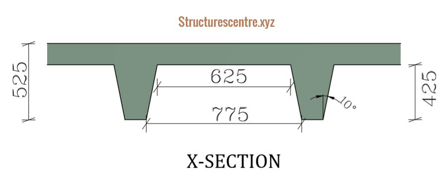
The average self-weight of a waffle slab can be determined from expression 1 using figure 1. or alternatively may be obtained from tables provided by mould specialists showing the mould dimensions against the estimated self-weight of the slab based on the spacing between ribs.
The waffle slab is formed through the use of special moulds, the dimensions can be obtained from a mould specialist, this includes the width, depth and volume of void per mould. Generally, the standard moulds are 225mm up to 425mm deep with toppings of 50mm – 100mm.

{ f}_{ s }=\frac { 25 }{ zy } \left\{ zyh-n\left[ \frac { s }{ 3 } \left( { a }^{ 2 }+{ b }^{ 2 }+\sqrt { { a }^{ 2 }{ b }^{ 2 } } \right) \right] \right\}{ f }_{ s }= self\quad weight\quad of\quad floor\quad (kN/{ m }^{ 2 })\\ n=number\quad of\quad wafflesAnalysis and Design
Contrary to common knowledge, a waffle slab ought to be analyzed and designed as a flat slab rather than a two-way restrained slab even though its behaviour is more of a two-way restrained slab. This is because the torsional stiffness of a typical waffle slab is considerably lower than the equivalent two way restrained slab. Hence, the coefficients for two way restrained slabs may overestimate the torsional restraints offered by the slab edges and might not be appropriate, especially where wide band beams are the preferred choice for beams . However, where the waffle slab is supported on beams which can be guaranteed to resist torsion at the corners, coefficients for two ways restrained slabs may be used. In the case of waffle slabs supported directly on columns, the slab must be analyzed and designed completely as a flat slab.
As with one way ribbed slabs, the ribs in waffle slabs are basically beams and the rules for beam design are followed. The section is designed as a solid section at the support (rectangular beam) and as a flanged section at the span. Light reinforcement or fabric mesh based on the
Worked Example
The waffle floor shown in figure 2a & b is required for a shopping mall building. Preliminary sizing of the floor has been carried out by selecting a suitable mould and the slab dimensioned as shown in the figures. The floor is to be constructed from C25/30 concrete and steel bars having a yield strength of 460mpa.

Guidance on sizing waffle slabs can be found in the concrete Centre publication: Economic concrete frame elements.
Actions
The size of the chosen mould is indicated in figure 2b, and the size of the components determined, therefore the actions on this floor can be determined.
Permanent Actions
a.\quad{ f}_{ s } =\frac { 25 }{ yz } \left\{ yzh-n\left[ \frac { s }{ 3 } \left( { a }^{ 2 }+{ b }^{ 2 }+\sqrt { { a }^{ 2 }{ b }^{ 2 } } \right) \right] \right\} =\frac { 25 }{ 9.6\times 12 } \left( 9.6\times 12\times 0.525-(11.66\times 9) \right) \times \\ \left( \frac { 0.425 }{ 3 } \left( { 0.775 }^{ 2 }+{ 0.625 }^{ 2 } \right) +\sqrt { 0.23 } \right) =8.36kN/{ m }^{ 2 }b.finshes\quad \& \quad services\quad =1.5kN/{ m }^{ 2 }Permanent\quad Actions\quad { g }_{ k }=8.36+1.5\\=9.86kN/{ m }^{ 2 }Variable Actions
Imposed\quad loads(malls)\quad { q }_{ k }=4kN/{ m }^{ 2 }Design Value of Actions
By inspection the permanent actions are less than 4.5 times the variable actions, therefore equation 6.10b of BS EN 1991-1-1 can be used.
{ n }_{ s }=1.35\xi { g }_{ k }+1.5{ q }_{ k }=(1.35\times 0.925\times 9.86)+(1.5\times 4)\\=18.3{ kN }/{ m }^{ 2 }There are wide beams along the column strip which can be designed to resist torsion at the slab corners. Hence, the slab can be designed as a two
The corner panels are more critical, hence only the design of this panel is presented in this post. You’re encouraged to complete the design of the other panels following the same
Flexural Design
The coefficients for two way restrained slab are used to obtain the critical moment and shear forces in the slab. For the corner panels, the coefficient used is that of two adjacent sides discontinuous.
\frac { { l }_{ y } }{ { l }_{ x } } =\frac { 12 }{ 9.6 } =1.25coefficients=\quad -0.066\quad \& \quad 0.049
Negative Moment at Supports
{ M }_{ Ed }=\left( 0.066\times 18.3\times { 9.6 }^{ 2 } \right) \times 0.9\\=100.2kN.m/ribsAssuming the cover to reinforcement is 25mm and 12mm bars with 8mm links. The effective depth is
d=\left( h-{ c }_{ nom }+\frac { \phi }{ 2 } +links \right) \\=525-(25+12/2+8)=486mmk=\frac { { M }_{ Ed } }{ { bd }^{ 2 }{ f }_{ ck } } =\frac { 100.2\times { 10 }^{ 6 } }{ 900\times { 486 }^{ 2 }\times 25 } =0.019z=d\left( 0.5+\sqrt { 0.25-0.882k } \right) \le 0.95=0.95d=0.95\times 486=461.7mm
{ A }_{ s }=\frac { { M }_{ Ed } }{ 0.87{ f }_{ yk }z } =\frac { 100.2\times { 10 }^{ 6 } }{ 0.87\times 460\times 461.7 } \\=542.3{ mm }^{ 2 }Try\quad 5Y12/ribs\left( { A }_{ s,prov }=565{ mm }^{ 2 } \right) \\ Spread\quad across\quad effective\quad width\quad of\quad ribsPositive Moment in Span
{ M }_{ Ed }=\left( 0.049\times 18.3\times { 9.6 }^{ 2 } \right) \times 0.9=\\74.38kN.m/ribsAssuming the cover to reinforcement is 25mm and two layers of 12mm bars with 8mm links. The effective depth is
d=\left( h-{ c }_{ nom }+\frac { \phi }{ 2 } +{\phi}+links \right) \\=525-(25+12/2+12+8)\\=474mmk=\frac { { M }_{ Ed } }{ { bd }^{ 2 }{ f }_{ ck } } =\frac { 74.38\times { 10 }^{ 6 } }{ 900\times { 486 }^{ 2 }\times 25 } =0.014z=d\left( 0.5+\sqrt { 0.25-0.882k } \right) \le 0.95=0.95d=0.95\times 474=450.3mm
{ A }_{ s }=\frac { { M }_{ Ed } }{ 0.87{ f }_{ yk }z } =\frac { 74.38\times { 10 }^{ 6 } }{ 0.87\times 460\times 450.3 } \\=412.74{ mm }^{ 2 }Try\quad 4Y12/ribs\quad \left( { A }_{ s,prov }=452{ mm }^{ 2 } \right) \\ in\quad two\quad layersShear Design
{ V }_{ Ed }=\left( 0.49\times 18.3\times 9.6 \right) \times 0.9=77.5kN{ V }_{ Rd,c }=0.12k\left( 100\rho { f }_{ ck } \right) ^{ \frac { 1 }{ 3 } }{ b }_{ w }d\ge { V }_{ min }{ b }_{ w }=125+2cTan\theta =125+2\times 41Tan10\\=139.5mmk=1+\sqrt { \frac { 200 }{ d } } =1+\sqrt { \frac { 200 }{ 486 } } =1.64<2\rho =\frac { { A }_{ s } }{ { b }_{ w }d } =\frac { 226 }{ 139.5\times 486 } =0.0033\quad \\(assuming\quad 2H12){ V }_{ Rd,c }=0.12\times 1.64\left( 0.33\times 25 \right) ^{ \frac { 1 }{ 3 } }\cdot 139.5\times 486\\ =26.95kN{ V }_{ min }=0.035{ k }^{ 3/2 }\sqrt { { f }_{ ck } } { b }_{ w }d=0.035\times 1.64^{ 3/2 }\sqrt { 25 } \cdot 139.46\times 486=24.91kN \left( { V }_{ Ed }>{ V }_{ Rd } \right) \quad \left( 77.5>26.96 \right)Hence\quad shear\quad rebar\quad is\quad needed
Shear Reinforcement
\theta =0.5{ sin }^{ -1 }\left( \frac { { 5.56V }_{ Ed } }{ { b }_{ w }d\left( 1-{ f }_{ ck }/250 \right) { f }_{ ck } } \right)\theta =0.5{ sin }^{ -1 }\left( \frac { 5.56\times 77.5\times { 10 }^{ 6 } }{ 139.5\times 486\left( 1-25/250 \right) 25 } \right) \\=8.20^{ \circ }cot\theta =6.94>2.5\quad therefore\quad cot\theta =2.5
\quad z=0.9d=0.9\times 486=437.4mm
\frac { { A }_{ sv } }{ { s }_{ v } } \ge \frac { { V }_{ Ed } }{ z{ f }_{ ywd }cot\theta } =\frac { 77.5\times { 10 }^{ 3 } }{ 437.4\times 460\times 2.5 } \\=0.15 max\quad spacing\quad { s }_{ v }=0.75d=0.75\times 486\\=364.5mmUse\quad Y8-300mm\quad centres\quad (0.34)
Deflection Verification
Limiting (L/d)
\left[ \frac { l }{ d } \right] _{ limit }=N\cdot k\cdot F1\cdot F2\cdot F3\rho =\frac { { A }_{ s,req } }{ { A }_{ c } }=\frac { 412.74 }{ \left( 900\times 100 \right) +\left( 139.46\times 425 \right) } =0.0028{ \rho }_{ o }={ 10 }^{ -3 }\sqrt { { f }_{ ck } } ={ 10 }^{ -3 }\sqrt { 25 } =0.005N=\left[ 11+\frac { 1.5\sqrt { { f }_{ ck } } { \rho }_{ o } }{ \rho } +3.2\sqrt { { f }_{ ck } } \left( \frac { { \rho }_{ o } }{ \rho } -1 \right) ^{ \frac { 3 }{ 2 } } \right] =\left[ 11+\frac { 1.5\sqrt { 25 } \cdot 5 }{ 2.8 } +3.2\sqrt { 25 } \left( \frac { 5 }{ 2.8 } -1 \right) ^{ \frac { 3 }{ 2 } } \right]N=35.53
k=1.3(end\quad span)
F1=0.82\quad ;\quad F2=\frac { 7 }{ l } =\frac { 7 }{ 9.6 } =0.73F3=\frac { 310 }{ { \sigma }_{ s } } \le 1.5 { \sigma }_{ s }=\frac { { f }_{ yk } }{ { \gamma }_{ s } } \left[ \frac { { g }_{ K }+{ \psi q }_{ k } }{ { n }_{ s } } \right] \left( \frac { { A }_{ s,req } }{ { A }_{ s,pro } } \right) \cdot \frac { 1 }{ \delta } =\frac { 460 }{ 1.15 } \left[ \frac { 9.86+0.6(4) }{ 18.3 } \right] \cdot \frac { 412.74 }{ 452 } =244.7MpaF3=\frac { 310 }{ 244.7 } =1.27\left[ \frac { l }{ d } \right] _{ limit }=35.53\times 1.3\times 0.82\times 0.73\times 1.27\\=35.11Actual (L/d)
{ \left[ \frac { l }{ d } \right] }_{ Actual }=\frac { span }{ effective\quad depth } =\frac { 9600 }{ 474 } \\=20.25Since the limiting value of l/d is greater than the actual l/d therefore deflection is satisfied in this slab.
Detailing Requirements
Minimum Area of Steel
{ A }_{ s }=0.26\frac { { f }_{ ctm } }{ { f }_{ yk } } { b }_{ t }d\ge 0.0013{ b }_{ t }d{ f }_{ ctm }=2.56Mpa{ A }_{ s }=0.26\frac { 2.56 }{ 460 } \cdot { 10 }^{ 3 }\times 100\ge 0.0013\cdot { 10 }^{ 3 }\times 100 \\=144.5{ mm }^{ 2 }/mUse\quad A142\quad Mesh\quad in\quad Topping
Crack Control
stress\quad in\quad bars\quad { \sigma }_{ s }=245Mpamaximum\quad crack\quad width\quad =0.4mm\quad o.k
This concludes this design example. The detailing of the typical corner panel has been attached as a pdf file. You’re encouraged to complete the design of the other panels and finish up the detailing.
You might also like Designing a Trough(Ribbed Slabs): Designing a Trough Slab-Worked Example.
THANK YOU FOR READING!!! COMMENT & SHARE THIS POST IF YOU LIKE IT.
tadalafil 10mg tablets in india – liquid tadalafil generic cialis us
how much is the generic viagra – viagra in usa prescription sildenafil buy canada
cialis online pharmacy india – canadian neighbor pharmacy tadalafil 20 mg in canada
ivermectin cost in usa – stromectol pill ivermectin india
best real casino online – free slots online slot machine
best ed medications – mensedppl.com ed medication online
prednisone steroid – how much is prednisone in mexico prednisone 15 mg daily
how to buy cialis without a prescription – Free cialis medicine tadalafil tablets
ivermectin 400 mg – buy stromectol for humans australia ivermectin purchase
ed pills at cvs – ed and diabetes best treatment for ed
ventolin hfa inhaler – ventolin medication buy albuterol online
cytotec tablet price in india – cytotec medicine price in india cytotec over the counter canada
I’m amazed, I have to admit. Rarely do I come across a blog that’s both educative and engaging, and without a doubt,
you have hit the nail on the head. The problem is something which too few men and women are speaking intelligently about.
I am very happy I stumbled across this during my search for
something regarding this.
doxycycline online paypal – doxycycline 100mg price uk doxycycline otc
medicine neurontin capsules – neurontin 200 mg price synthroid 25 mg coupon
order viagra online without – generic viagra online purchase in usa
rx cialis canada – cistrongp tadalafil 20mg in india
buy vardenafil online order – generic vardenafil 10 mg generic vardenafil online
buy cialis 5mg
Zithromax Good For Strep Throat
stromectol tablets for sale – ivermectin 50ml india ivermectin
generic prednisone 20mg – prednisone 250 mg over the counter prednisone no prescription
buy generic accutane online cheap – order accutane no prescription accutane australia buy online
buy amoxicillina noscript – generic amoxicillin at walmart amoxicillin without a doctor’s prescription
la viagra es peligrosa
medrol buy – medrol 16 can i buy lyrica online
https://buytadalafshop.com/ – Cialis
sildenafil generic costs – Buy online viagra sildenafil 100 mg best price
https://buysildenshop.com/ – Viagra
average cost cialis – Price cialis cialis usa over the counter
Can Amoxicillin Kill A Std
stromectol 12mg – ivermectin medication stromectol covid
deltasone 10 mg cost – prednisone order prices for prednisone