Slab raft is the simplest form of raft foundation typically encountered in practice. The motivation as with other raft foundation is to bring applied pressures to acceptable limits.
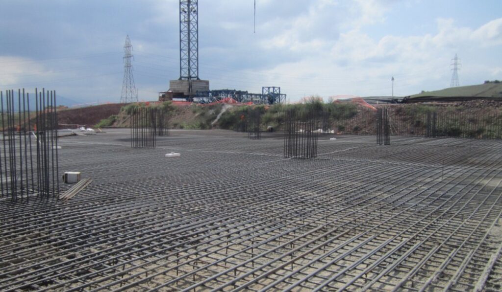
Another variant of the family of raft foundations is the slab raft. The slab raft is a type of raft foundation where a flat slab is used to span at least the entire footprint of a structure, supporting all structural loads, and ultimately delivering them to the bearing stratum. Slab rafts are the simplest form of raft foundation typically encountered in practice (See: Foundation Types: Selecting a Foundation). They are usually required or used, where although a structure is relatively lightly loaded, necessitates a raft foundation. This can by virtue of the bearing stratum having a very poor bearing capacity or a situation that result in very closely spaced bases if isolated-spread foundation is used. Thus, the incentive as with every other raft foundation is to bring the applied pressures to acceptable limits by spreading the structural loads over a wider area.
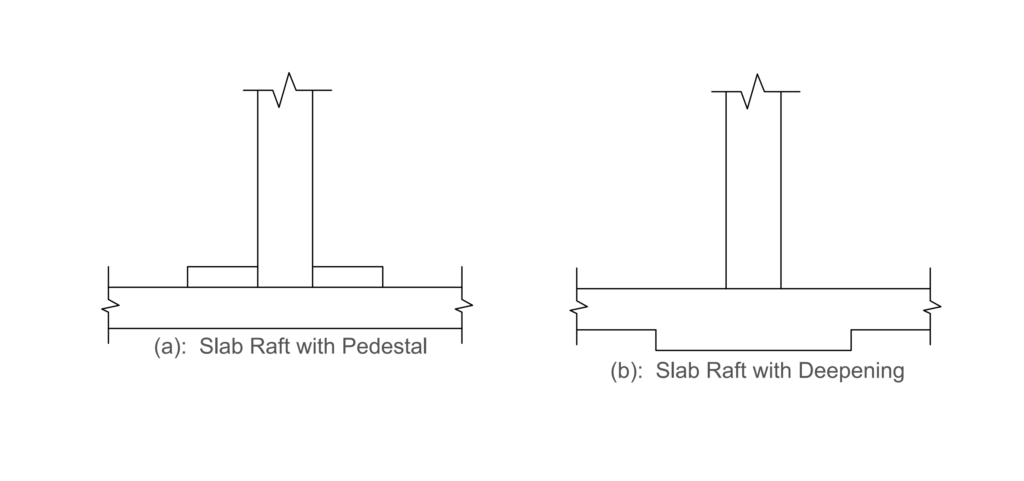
Slab rafts are essentially a flat slab with uniform thickness (typically in the range of 150 -300mm thick). This thickness is often determined by punching shears which are often large at the column positions. Where the punching shears are very high, pedestals or a deepening may be provided at the columns base to enhance the punching shear resistance (See figure 1).
Analysis of Slab Raft
There are two approaches to raft foundation design: the conventional rigid method or the flexible method.
Flexible Method
The flexible approach assumes that the raft is flexible relative to the supporting soil, the contact pressure is anything but uniform and the deflection of the raft slab will vary with location. This is often idealized using the beam on elastic foundation theory. Here the elastic properties of the soil are taking into full consideration.
The flexible method of analyzing raft is beyond the subject of this article, hence will not be considered further.
Rigid Method
The rigid method on the flip side assumes that the raft is stiff relative to the soil, hence the raft can idealize as a fully rigid member without any consideration of the elastic properties of the soil and its interaction with the structure. In theory, either of the flexible or rigid approach can be used to design a raft, however, in reality no raft is wholly flexible nor is it totally rigid, these are merely reasonable assumptions that lies completely within the remit of the designer. One which the designers must always consider judiciously.
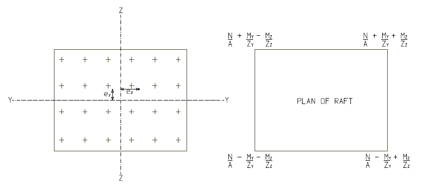
In analyzing a slab raft using the conventional rigid method, the whole slab is analyzed as a large beam member by summing up all column loads on each line. This column loads are then applied on the beam member to determine the eccentricity of the resultant of the column loads from the centroid of the slab, which is used to compute ground pressures using the following equation (Figure 2).
\sigma =\frac { N }{ A } \pm \frac { { M }_{ y } }{ { Z }_{ y } } \pm \frac { { M }_{ z } }{ { Z }_{ z } } Design of Slab Raft
Slab rafts are generally designed as an inverted flat slab floor subjected to the earth bearing pressure at ULS. The slab is divided into column and middle strips, and the corresponding reinforcement is provided. Punching shear is also verified around the column junctions and control perimeter. In summary, all rules, as they apply to the design of flat slab, also apply.
The design of flat slab has been covered in a previous article (See: Designing a Flat Slab – Worked Example). The reader unfamiliar with the design of flat slab should consider looking up the aforementioned article before considering the remaining part of this article.
Worked Example
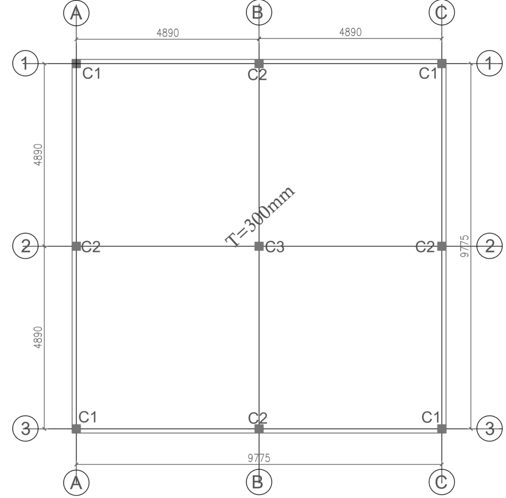
A proposed two-storey frame (Figure 3) is to be founded on a very poor soil stratum. A slab raft has been recommended for the foundation. Using the data presented in the table provided below, use approximate hand calculations to establish the quantity of the reinforcement required in the raft foundation.
| Column | Gk (kN) | Qk (kN) |
| C1 (225x225) | 159 | 62 |
| C2 (225x225) | 215 | 103 |
| C3 (225x225) | 421 | 198 |
- Bearing resistance = 40kN/m2
- Density of fill = 18kN/m3
- Concrete = C20/25, fy = 410Mpa
- Raft Slab = 300mm
Serviceability Limit State
Permanent Actions
G_{k,cols} = 4\left( 159 \right) +4\left( 215 \right) +\left( 421 \right) \\=1917kNG_{k,slab}=0.3\times 10\times 10\times 25\\=750kNG_{k}=G_{k,cols}+G_{k,slab}\\=1917+750=2667kNVariable Actions
Q_{k,col} =4\left( 62 \right) +4\left( 103 \right) +\left( 198 \right) \\ Q_{k}=858kNTotal Actions @ SLS
N_{SLS} = G_{k}+Q_{k}=2667+858\\=3525kNPressure Check
\sigma =\frac { N }{ A } \pm \frac { { M }_{ y } }{ { Z }_{ y } } \pm \frac { { M }_{ z } }{ { Z }_{ z } } =\frac { 3525 }{ (10\times 10) } =35.25kN/{ m }^{ 2 }\left( \sigma =35.25kN/{ m }^{ 2 } \right) <\left( { p }_{ T }=40kN/{ m }^{ 2 } \right)Ultimate Limit State
Total Actions @ ULS
N_{k} =\left( 1.35( 2667 \right) +\left( 1.5\times 858 \right)\\ =4887.5kNBearing pressure @ULS
{ \quad \sigma }_{ max }=\frac { N }{ A } \pm \frac { { M }_{ y } }{ { Z }_{ y } } \pm \frac { { M }_{ z } }{ { Z }_{ z } } =\frac { 4887.5 }{ (10\times 10) } =48.9kN/{ m }^{ 2 }Raft Slab Design
The raft slab is designed as a flat slab subjected to an upward pressure of (48.9kN/m2) in accordance with code provisions. Note that in this case, the load is acting upwards, hence the tensile reinforcement required in the span would be positioned at the top while those required at the supports are fixed at the bottom.
Structural Analysis
The raft slab can be analyzed as part of a subframe or through the use of coefficients. In this example simple coefficients are used to determine the bending moments and shear forces.
Consider the slab strip on the column grid 2-2 (typical for B-B).
strip\quad width = (4.9+4.9)/2 =4.9m
{ w }_{ max }={ n }_{ s,max }\cdot width=48.9\times 4.9\\=239.61kN/mUtilizing the coefficient for bending moment and shear force for flat slabs, we have
Negative moment @ supports
M=-0.086\times239.61\times 4.9^2\\=-494.8kN.m
Positive moment in span
M=0.086\times239.61\times 4.9^2\\=494.8kN.m
Maximum shear force
V_{max}=0.5\times239.61\times 4.9 = 587kNFlexural Design
Recall that the slab is divided into middle and column strip. Thus, the moment is apportioned between the column and middle strips. For this strip, the negative moment at supports will be shared in the proportion of 70% to the column strip and 30% to the middle strip while the positive moment in the spans will be shared in the proportion of 50-50%.
Assuming 12mm bars in both directions and concrete cover of 25mm, we can determine the mean effective depth as:
{ d }_{ y }=h-(c+\phi /2)\\=300-(25+12/2)=269mm { d }_{ z }=h-(c+\phi /2+\Phi )\\=275-(25+12/2+12)=257mm{ d }_{ min }=\frac { { d }_{ y }+{ d }_{ z } }{ 2 } =\frac { 269+257 }{ 2 } =263mmPositive moment in spans
width of column strip = (4.9/4 +4.9/4) = 2.45m
width of midle strip = 4.9-2.45 =2.45m
M=494.8kN.m
Positive moment in column strip
{ M }_{ Ed }=0.5\times \frac { 494.8 }{ 2.45 } =101kN.m/mk=\frac { { M }_{ Ed } }{ b{ d }^{ 2 }{ f }_{ ck } } =\frac { 101\times { 10 }^{ 6 } }{ { 10 }^{ 3 }\times { 263 }^{ 2 }\times 20 } =0.073=0.95d=0.93\times 263=244.6mm
{ A }_{ s }=\frac { { M }_{ Ed } }{ 0.87{ f }_{ yk }z } =\frac { 101\times { 10 }^{ 6 } }{ 0.87\times 410\times 244.6 } \\=1157.6{ mm }^{ 2 }/mUse T16mm bars @ 150mm Centers Bottom (As, prov = 1340mm2)
Positive moment in middle strip
{ M }_{ Ed }=0.5\times \frac { 494.8 }{ 2.45 } =101kN.m/mSince the magnitude of the bending moment is same as in column strip above, we can use same reinforcement for the middle strip.
Use T16mm bars @ 150mm Centers Top (As, prov = 1340mm2)
Negative moment in supports.
M=-494.8kN.m
Negative Moment in column strip
{ M }_{ Ed }=0.7\times \frac { 494.8 }{ 2.45 } =141.4kN.m/mk=\frac { { M }_{ Ed } }{ b{ d }^{ 2 }{ f }_{ ck } } =\frac { 141.4\times { 10 }^{ 6 } }{ { 10 }^{ 3 }\times { 263 }^{ 2 }\times 20 } =0.10=0.9d=0.9\times 263=236.7mm
{ A }_{ s }=\frac { { M }_{ Ed } }{ 0.87{ f }_{ yk }z } =\frac { 141.4\times { 10 }^{ 6 } }{ 0.87\times 410\times 236.7 } \\=1674.7{ mm }^{ 2 }/mUse T16mm bars @ 100mm Centers Bottom (As, prov = 2010mm2)
Negative Moment in middle strip
{ M }_{ Ed }=0.3\times \frac { 494.8 }{ 2.45 } =60.6kN.m/mk=\frac { { M }_{ Ed } }{ b{ d }^{ 2 }{ f }_{ ck } } =\frac { 60.6\times { 10 }^{ 6 } }{ { 10 }^{ 3 }\times { 263 }^{ 2 }\times 20 } =0.04z=0.95d =0.95\times 263=249.9mm
{ A }_{ s }=\frac { { M }_{ Ed } }{ 0.87{ f }_{ yk }z } =\frac { 60.6\times { 10 }^{ 6 } }{ 0.87\times 410\times 249.9 } \\=679.8{ mm }^{ 2 }/mUse T12mm bars @ 150mm Centers Bottom (As, prov = 753mm2)
Having determined the quantity of steel required in the column and middle strip of the slab foundation, we must verify resistance of the slab to punching.
Punching Verification
In this example, punching shear, by inspection appear to be more critical on column C3. Thus, only column C3 is considered. Punching will be verified at two locations: the column interface and the critical control perimeter-2d from the column interface.
@ Column Interface
Verify\quad that\quad { N }_{ ED }\le { V }_{ RD,max }N_{Ed} = (1.35\times421)+(1.35\times198)\\=835.7kN{ V }_{ RD,max }=0.2\left[ 1-\frac { { f }_{ ck } }{ 250 } \right] { f }_{ ck }pd0.2\left[ 1-\frac { 20 }{ 250 } \right] 20\cdot (4\times 300)\times 263\times { 10 }^{ -3 }\\1161.4kN({ N }_{ ED }=835.7kN)<({ V }_{ Rd,max }=1161.4kN@ Basic control perimeter 2.0d
verify\quad{ v }_{ ED }\le { v }_{ RD,c }{ v }_{ ED }=\frac { { V }_{ ED } }{ { u }_{ 1 }d } \quad \\where\quad { V }_{ ED }={ N }_{ ED }-{ \triangle V }_{ ED }\triangle { V }_{ ED }=pAA={ c }_{ 1 }{ c }_{ 2 }+\pi { \left( 2d \right) }^{ 2 }+4({ c }_{ 1 }+{ c }_{ 2 })d\\
= 300^2+\pi(2\times263)^2+4(300+300)263\\=1.59m^2\triangle { V }_{ ED }=pA=48.9\times1.59=77.75kN { V }_{ ED }={ N }_{ ED }-{ \triangle V }_{ ED } \\= 835.7-77.75=758kN{ p }_{ 1 }=2({ c }_{ 1 }+{ c }_{ 2 })+4\pi { d }\\=2(300+300)+4\pi ({ 263 })=4506.3mm{ v }_{ ED }=\frac { 758\times { 10 }^{ 3 } }{ 4506.3\times 263 } =0.64mpaTo determine the concrete shear resistance:
{ v }_{ RD.c }=0.12k(100\rho { f }_{ ck })^{ 1/3 }\ge 0.035{ k }^{ 3/2 }\sqrt { { f }_{ ck } } k=1+\sqrt { \frac { 200 }{ d } } =1+\sqrt { \frac { 200 }{ 263 } } =1.87<2\rho =\frac { { A }_{ s } }{ bd } =\frac { 2010 }{ { 10 }^{ 3 }\times 263 } =7.6\times { 10 }^{ -3 }{ v }_{ RD,c }=0.12\cdot 1.87(100\cdot 7.6\times 10^{ -3 }\times 20)^{ 1/3 }\\\ge 0.035\times { 1.87 }^{ 3/2 }\sqrt { 20 } =0.56mpa{ (v }_{ ED }=0.64mpa)>({ v }_{ RD,c }=0.56mpa)Since the applied punching shear is greater than the concrete shear resistance, punching reinforcement is required. This is to be provided along the basic control perimeter. See Designing for Punching Shear in Concrete Slabs for procedure.
See: Designing a Beam Strip Raft Foundation
Design Resume
Note that only the strips on gridlines 2-2 (typical for strips B-B) has been presented. Before the design of the slab is completed, the strips on gridlines 1-1 (typical for 2-2, A-A & C-C) must be designed following similar procedures. It is after this, can the slab be detailed, considering all guidelines and detailing rules as may be applicable to flat slabs.