Precast bridges are highly favoured, where the speed of construction is very crucial or where the cost of procuring precast is justified by a shorter construction programme. This article discusses the different forms of precast bridges, typically encountered in practice.
With regards to construction methodology, concrete bridges can be classified into two categories – ‘cast in place’ and ‘precast.’ Cast in place bridges are those in which the concrete for the bridge structure is poured and cured on-site in it finished position. Precast bridges on the other hand uses prefabrication techniques. The concrete is poured and cured offsite after which it is transported to site and erected into position.
In this article, the focus is on precast bridges, there is an existing article explaining the several forms of cast in place/in-situ concrete bridges – (See: Construction of Cast in Place Bridges). There are at least 5 types of precast bridges. These include:
- Standard precast beam bridges1
- Bespoke precast beam bridges1
- Precast segmental bridges1
- Whole span precast bridges1
- Incrementally launched bridges1.
The above-named options are bridge solutions utilized wherever the speed of construction is very crucial or generally where the cost of procuring precast is justified by shorter construction programme or simpler construction process. Precast bridges, generally, are commonly produced at a rate of 20-25m/week, which is about twice the rate that can be achieved with most in situ solutions1. In fact, this rate can be increased to 50-100m/week as long as there is sufficient length of bridge to justify further capital investment1.
Standard Precast Beam Bridges
As the name would seem to suggest, standard precast beam bridges use standard precast sections that are manufactured off-site and erected using cranes into position. This form of bridge construction utilizes pre-tensioned beams which are typically straight. They are ideal for relatively small span arrangement, ranging from 5-40m. In highway bridges, their span-depth ratio typically ranges between 15 -18 because they are generally simply supported1. However, sometimes they can be designed and constructed to be continuous over supports, in which case the span-depth ratio can be increased to 201.
Standard beam bridges, although very economical for a wide range of spans are often limited by the length of precast section that can be transported. Hence, they are best suited for low lying site with a very good access.
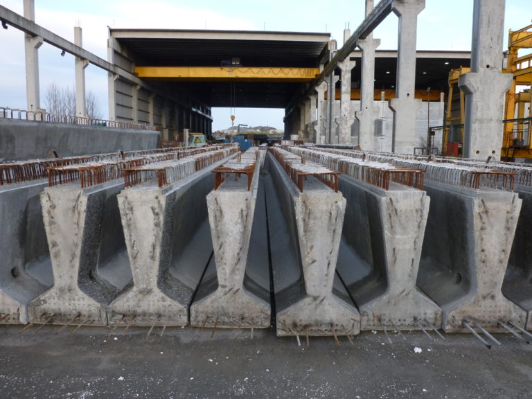
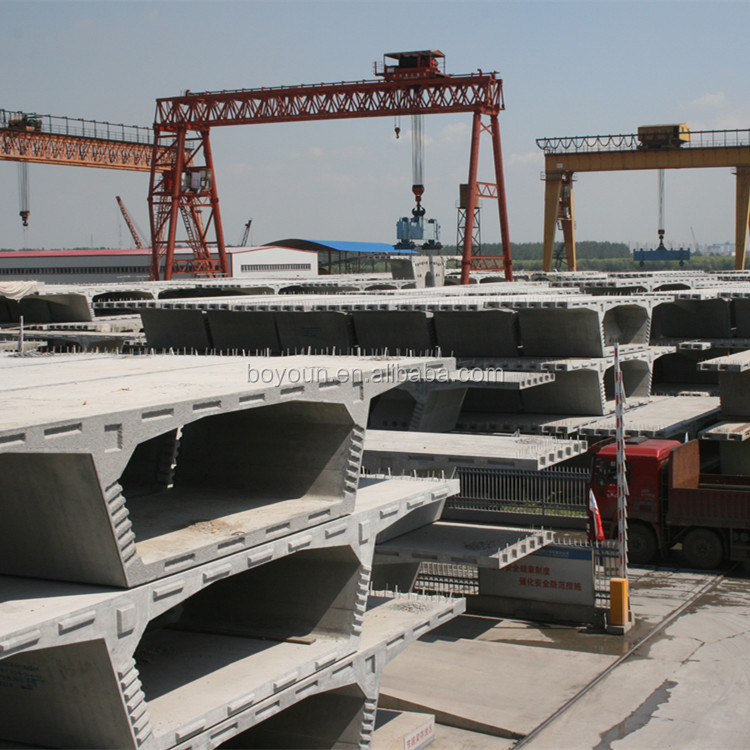
Precast beam sections typically encountered in the practice of constructing the standard beam bridges include, Inverted T beams, M beams, U beams, Y beams and the SY beams. The typical arrangement has any of the afore-listed beams spaced on a line of 1-2m apart with a top slab of approximately 160mm. In SY beams, however, the thickness of the slab increases to 175-225mm1 (Figure 1). The length of these beams is often dictated by the availability of access to the site, typically a value of 15-40m is used.
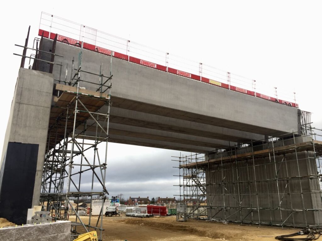
While standard precast beam bridges may have been designed as continuous over support in order to avoid the need for expansion joints, during construction, they are erected as simple spans (Figure 2). An in-situ stitch is then formed between the end of the beams thereby making the structure integral and monolithic. The implication of having a continuous structure, manifests in the form of hogging moment at the supports. However, this is catered for by the provision of top mat in the bridge slab. Some bottom reinforcement is also provided at the piers, as creep from prestressing secondary moment will induce a sagging effect. Continuity between beams is often ensured by lapping of the projecting lengths of prestressing strand, though reinforcement could also be used.
The primary advantage of the standard precast beam bridge is the ability to produce precast sections in a well-controlled environment, with the only on-site activity being the casting of the deck slab. A second advantage is that construction can be started at several locations at the same time if needed, thereby reducing the total programme time. Overall, standard precast beam bridges are very cost-effective solution, provided the span is relatively small and there is good access.
Bespoke Precast Beam Bridges
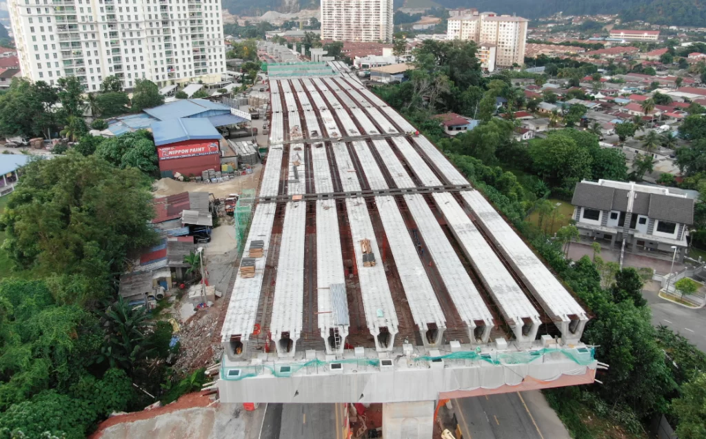
This precast bridge option utilizes bespoke precast beam section which can be either manufactured on-site or off-site. They are typical for medium spans ranging from 30-60m and are very similar to the standard precast beam solutions. Except that the precast beams are significantly heavier and can be either pre-tensioned or post-tensioned. Here, the precast beam sections utilize smaller webs, have a more effective section and better aesthetic feel than the standard precast beam bridges. They also represent a very good solution for bigger spans relative to standard precast beam bridges. With low lying sites with good access, crane erection is possible, however with bigger site, erection using a gantry becomes imminent.
Typical precast beam sections used include U, I and T beams (Figure 3) which are typically spaced on a line of 2-4m with a top slab which is at least 200mm thick to complete the arrangement 1. Because bespoke precast beam bridges allow for this use of post-tensioning, it follows that shear relief is obtained from the inclined cables, thereby allowing for thinner webs to be used.
With respect to erection, one way of doing it, is in a similar fashion to the standard precast solutions via the use of crane or gantry, with an in-situ reinforced concrete stitch formed at the beam ends to make them continuous. Another way of doing it is using the balanced cantilever technique. While cranes may be able to accommodate bespoke precast beams weighing up to 150t, anything beyond this threshold will require the use of a gantry for the erection procedure1. However, the use of a gantry can only be justified, from the perspective of cost effectiveness if the deck area is above 10,000m2.
In summary bespoke precast beam bridges offers similar advantage to the standard precast solution. However, when compared with the standard precast solution, with increase in span, bespoke precast bridges are more effective and economical. Overall bespoke beam bridges are very cost effective depending on access to the site and amount of temporary works required to work.
Precast Segmental Bridges
Precast segmental bridges utilize short box sections which are manufactured in factory-controlled environment on-site. They are typically well suited for medium to long span with the range of 30-200m1. The box sections, produced in segments are post-tensioned and are able to accommodate any variation in depth. Span to depth ratio for segmental bridges, varies within the sections of the bridge, typically it ranges anywhere between 15-22. In precast segmental bridges the box section has a minimum web width of 300mm in contrast to the in-situ option with a higher minimum web width, because there is more control in a factory setting.
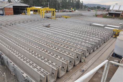
During construction, the box segments are cast in steel moulds. The segments are match against each other in a sequence that is in accordance with the way they are to be erected. Each new segment is cast between a fixed bulkhead and the previously cast segment, with the alignment being incorporated by small angular changes between these two segments (Figure 4). The segments are then stored before being transported to the site for erection. The amount of storage depends on the rate of casting and erection relative to each other.
Erection of segmental bridges can take two approaches – span by span and balanced cantilever, depending on the availability of access to the site. Span-span involves erecting the box segments on a span-by-span basis using a gantry, it is typically suitable for bridges with spans within the range of 25-60m. Whereas, balanced cantilever is used for bridges with spans of 30-200m, with the segments erected using a crane or gantry.
To summarize, the primary advantage of segmental bridges is the savings associated with use of box segments that have being produced in a factory-controlled environment. They are an efficient solution, especially where the investment in the area of concreting and amount of erection equipment required is justified. There is no question that at large sites, segmental precast bridges deliver the most competitive construction costs.
Whole Span Precast Bridges
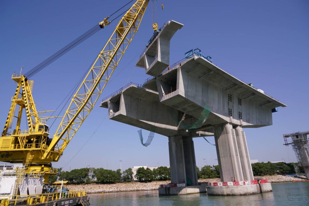
Whole span bridges are very similar to the segmental bridges except that it utilizes whole span boxes as against segmental boxes (Figure 5). They are very ideal for a medium span, anywhere from 30m to 60m. Whole span precast bridges are particularly suited for the longest schemes, covering deck areas of 50-100,000m2. In other words, they are best suited for railway lines and similar structures where the scale of the project justifies the required huge cost implications or where faster rates of production is needed.
For whole span bridges, the construction and erection procedures follow the same process as in segmental bridges. However, in whole span boxes, the weight of typical unit is 10-12times that of a segmental box. Steel moulds are typically used to cast the whole span, generally in a single pour. Alternatively, the bottom slab and the webs is cast on a first pour and the upper slab is cast subsequently. After production, gantries in the casting area are used to take the unit into storage. During erection, the boxes are taken along completed bridge deck using wheel boogies or rail system from which they are erected into position using an overhead gantry.
Whole span precast bridges offer similar advantage to the segmental precast solution, but they have an edge in terms of programme. Whole pan precast bridges, delivers a production rate of at least 100m/week, the fastest production rate achievable by any precast construction method.
Incrementally Launched Bridges
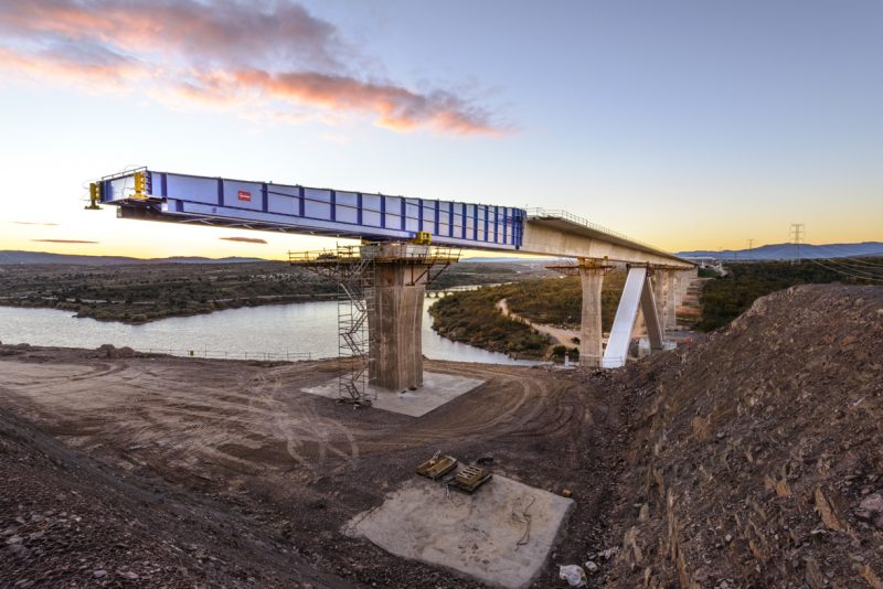
This bridge uses a box bridge which are generally cast behind the bridge abutment from which they are pushed or pulled into their final position. Incrementally launched bridges primary advantage is the non-requirement of falsework during casting of a spanned area (Figure 6). They have very good aesthetics, especially when inclined webs are used, and are very ideal where the cost of traditional falsework would be prohibitive. They are well suited for constant depth, medium spans, typically 30-80m, which are straight or have a constant curvature, in both plan and elevation. Generally, to use incremental launching, the bridge span should be at least 200m long with a deck area of at least 3000m2, even though maximum lengths of over 1000m are possible.
In sizing of the bridge, the web thickness is kept to at least 400mm, because every section of the bridge is bound to experience high shears during the launch. In fact, one of the major problems with incrementally launched bridges is that every section of the bridge is bound to experience significant forces during the construction. Thus, webs are often positioned directly above the temporary bearing locations, to ensure there are no moments in the section during a launch.
The typical span for launching is 40-50m, with maximum spans of about 80m, though such spans will need temporary props during launching. The main series of spans should, wherever possible, be of equal length. The length of each unit to be cast is chosen to suit the particular span. Typically, each 15-30m long unit is poured on a weekly cycle, even though it is possible to cast whole 40-50m spans on a two-weekly cycle. In either case, the typical production rates are about 25m/week.
Incrementally launched bridges offers a strong advantage for riverine sites where the use of falsework is to be avoided. The precast units are able to slide into place without any actual falsework.
Conclusion
In this article, several forms of precast bridges have been described, each of them has their unique features, advantages and disadvantages. The precast solutions when compared with cast-in-place solutions, one can easily deduce that they err on the part of the part of economy. However, the increased cost is often justified in the shorter programme and all other benefits typically associated with prefabrication.
Sources & Citation
- Concrete Bridge Development Group (2014) ‘Concrete Bridge Design & Construction Series No. 6: construction bridge construction method -Precast’, The structural engineer, 92(7).
- Concrete Bridge Development Group (2014) Technical Guide No. 14: Best construction methods for concrete bridge decks, Camberley, UK: CBDG (publication in 2014)