The primary function of every retaining wall is to resist the lateral forces from earth without any stability problems. The taller the retaining wall, the more likely that counterforts will become necessary to achieve stability. This article explains how to design a counterfort retaining wall.
Beyond 5m of soil retaining height, designing a retaining wall as a typical cantilever, results into a grossly economical structure. Aside the issues around the stability of the wall arising from overturning and sliding, the magnitude of the lateral forces occurring as a result of these heights ensures that the design bending moment and shear forces are going to be very large. So large such that designing the wall as a typical cantilever will result in a section that would be considered superfluous relative to the alternatives. Not just that the volume of concrete that would be required to ensure stability will be large, but the amount of reinforcement that would be required to satisfy the various limit states in the cantilever elements will also be large.
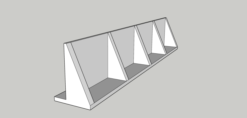
One of those alternatives that can be considered in place of typical cantilever retaining wall is the counterfort wall. A counterfort retaining wall is in fact, not different from the typical cantilever retaining wall. It still consists of all the typical elements that can be found in a typical cantilever retaining wall. Well, except that a counterfort retaining wall combines the stem, heel and toe with a triangular or trapezoidal stiffening element in the heel side of the retaining wall (Figure 1) known as ‘counterforts.’
A counterfort is basically a cantilever beam that serves the purpose of tying the wall’s stem and the wall base together. This way the internal stress distribution in the wall is greatly reduced while the stability of the wall is also enhanced.
This focus of this article is on designing a counterfort retaining wall. It is expected that the reader is already familiar with how to derive the actions acting on a retaining wall (See: Derivation of Actions to Retaining Wall Structures) and how to check the stability of a retaining wall (See: Structural Analysis of Retaining Walls). Most of the terminologies and equations contained within these articles are very valid and will be necessary when designing a counterfort retaining wall. Hence, you are encouraged to review both articles before proceeding beyond this point.
Proportioning a Counterfort Wall
In a counterfort retaining wall, for economical design, the spacing between the counterforts should be restricted to 50 – 66.7% of the retaining wall height. Also, other rules including those governing the proportioning of a typical cantilever retaining wall applies. For instance, the base width being estimated in the range of 66.7% of the soil retaining height and the footing width on the heel side being more than that of the toe side.
Stability
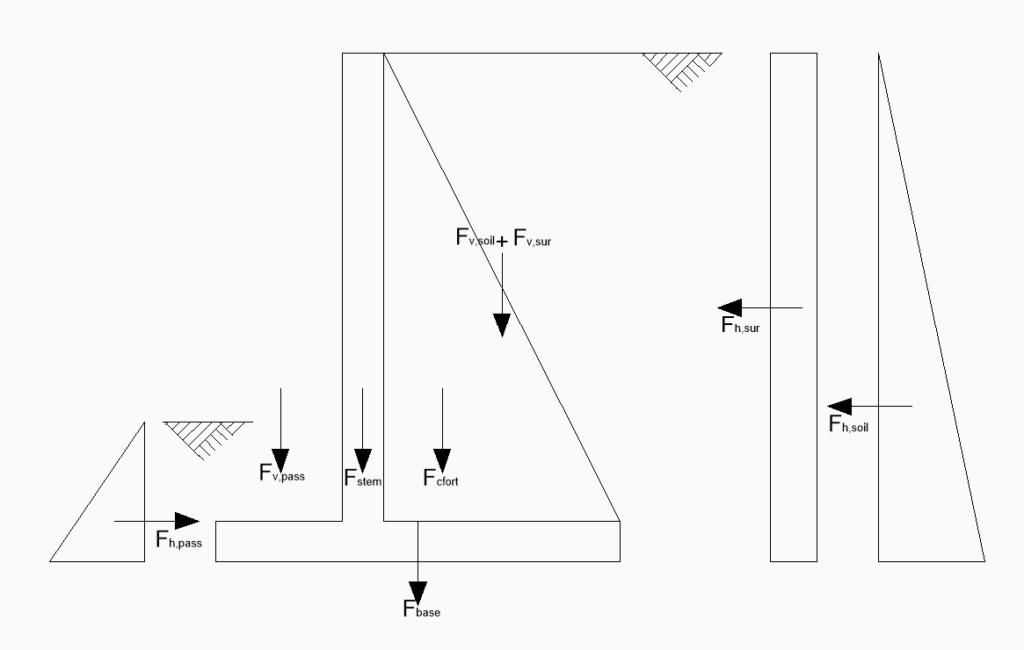
The stability of counterfort retaining wall is checked using the same procedure as a typical cantilever wall. Except, here, the weight of the counterfort is assumed to act as an integral unit with the wall. So, in computing the resistances to overturning, sliding and pressure, the weight of the counterfort is prorated based on the counterfort spacing and added to the resistances (See Figure 2)
Analysis of Counterfort Wall
As earlier stated, the influence of adding a counterfort element to a retaining wall is that the internal stress in the wall reduces. Indeed, a counterfort retaining wall is still a cantilever, but in this instance, the counterfort assumes the position of the cantilever while the wall becomes a two-way slab that is fixed at the base and both sides of the wall, and unsupported at the top of the wall. The heel by virtue of being tied by the counterfort is also a continuous two-way slab fixed at three ends and unsupported at one. The toe remains a cantilever as in the typical cantilever retaining wall and is analyzed as such.
Element Design
In the case of a counterfort retaining wall, there are four elements that will be designed within the structure. The stem, the heel, the toe and then the counterfort. This is explained below.
Designing the Stem
The stem can be conceptualized as a two-way fixed slab, fixed at either end where the wall crosses the counterforts and at the bottom, as was mentioned in the previous section. The maximum negative moment occurring on the wall must be determine, so also must the positive moment in the wall. The Foundation Engineering Handbook2 proposes a method for calculating this instant i.e., M =0.03kaγH3, which is essentially similar to the fixed end moment in a beam with a triangle loading. An alternative is to make use of charts. See the chart in Hugh Brookes’ Basics of Retaining Wall Design, appendix J. Results from this would be very accurate. But in most situations, the simplified equation above should be sufficient.
When detailing the wall, it should be noted that some continuity across counterforts exist, therefore it is suggested that the horizontal reinforcing be placed in the centre of the wall. Designing such horizontal reinforcing for a lateral pressure at one-half the wall height would also seem prudent. Theoretically, the pressure reduces near the top, but it is probably practical to use the same horizontal reinforcing full height. Use your judgment to detail the counterfort because the need for negative vertical reinforcing diminishes near the counterforts, as does horizontal reinforcing near the wall’s bottom.
Designing the Counterfort
Counterforts are essentially designed as a cantilever flanged beam. They are generally tapered, flaring from the top or slightly below the top of the wall/stem to near or at the edge of the heel. Most of the geometrical properties of the wall are predetermined. For instance, the span of the counterfort is the same as the height of the stem. While the counterfort overall depth is equal to the width of the heel which in turn is going to be determined by stability considerations. The only geometrical data that is not determined by the dimensions of the wall is the counterfort thickness which is often taking to be (300-400mm) thick.
In designing the Counterforts, the applied lateral action from the retained soil is distributed based on the tributary area between the counterforts. So that the internal forces can thus be determined using statics and because this forces lessons as we go up the wall, less reinforcing steel will also be required as the counterfort tapers to the top. Perhaps to design the counterfort the area of steel can be determined first at mid-height and then at the base. Alternatively, dowels can be provided to extend from the footing into the counterfort by about 1m based on the base shear and moment and then the moment and shear recalculated at this height. This is in order to obtain a lesser reinforcing steel which can then be provided for the remaining height of the counterfort.
Designing the Heel
The heel is designed as a longitudinal beam spanning between the counterforts with the appropriate uniform load being the net difference between the weight of the soil on the heel side any surcharge applied and the ultimate upward pressure on the heel side. Reinforcing steel is provided at the top in between counterforts and at the bottom under the counterforts. These is provided based on (M = 0.083WL2).
Designing the Toe
As earlier suggested, the toe is designed as a cantilever from the wall, similar to a conventional cantilever wall.
Steps in Designing a Counterfort Wall
- Establish the retained height, and geometry of retaining wall, including footing width, counterforts spacings and dimensions.
- Check the stability of the wall in overturning, sliding and pressure. The weight of the counterforts should be prorated based on spacing of the wall and added to in the stability calculations.
- Design the wall as a two-way slab fixed at the base.
- Design the toe as a cantilever.
- Design the heel as a longitudinal beam spanning between counterfort.
- Design the counterfort as a flanged cantilever beam.
Worked Example
A 7.5m tall counterfort retaining wall is to be constructed from C20/35 concrete and reinforced with 410Mpa high tensile steel bars. It is placed in a granular soil that has a density of 18kN/m3. The water table is below the level of the base to the retaining wall and there is a surcharge of 10 kN/m2 applied on the backfill. The angle of shear resistance φ is 30º, the coefficient of friction between the soil and the concrete is 0.57 and the bearing capacity of the soil is 250kN/m2. Size the retaining wall and determine the quantities of reinforcing steel required in the wall.
See the tab below for solution to the worked example.
The spreadsheet used for the calculation can be downloaded in the link below:
Password: structurescentre.com
Also See: Structural Aspect of Designing a Basement Wall
Sources & Citation
- Brookes H. (2010) Basics of Retaining Wall Design – a guide for the practicing engineer (8th Ed) CA. USA HBA publications Inc.
- Winterkorn and Fang (1975) Foundation Engineering Handbook.