
Introduction
Retaining structures or a retaining wall is any constructed wall that holds back soil a liquid or other materials where there is an abrupt change in elevation. Retaining walls have been used for thousands of years, in the construction of terraced fields on a steep slope, or a railway through a hillside, a retaining wall is used in some form or another. Their primary function is to provide lateral support to a backfill in order to maintain them in vertical position. Retaining walls are an absolute necessity where materials with tendencies to slide and repose at a particular inclination are to be retained.
Retaining walls have many applications, vis a vis:
- Swimming pools or underground septic tanks
- Wing walls & abutments
- Lateral support for embankment
- Construction of basement below ground level
Retaining walls can be grouped into three categories: gravity, embedded and hybrid. Structurally, they all perform the function of supporting a material, which is typically soil, at an angle that exceeds the angle of repose. Each type has unique properties making them ideally suited to specific situations.
Types of Retaining Walls
There are several types of retaining walls but the most common types are the cantilever retaining walls. Cantilevered retaining walls are classified as “yielding” because they are free to rotate without any lateral restraints. Cantilevered retaining walls are generally of masonry, concrete or both but can also take different forms as will be described subsequently.
Types of retaining walls include
Masonry or Concrete Walls: Masonry walls are usually either 8″ or 12″ concrete block masonry units, partially or solid grouted and reinforced. Higher walls require 12″ blocks and are often stepped back to 8″ as the retaining height reduces.
The stems of concrete walls must be formed, can be tapered for economy, usually with a taper in the inner face (earth side) to present a vertical exposed face.
Counter-fort Walls: Counterfort cantilever retaining walls incorporates wing walls projecting from the heel into the stems. The stems between counterforts is thinner and spans horizontally between the counterforts (wingwalls). The counterforts act as cantilevered element and are structurally efficient because the counterforts are tapered down to a wider deeper base where moments are higher. Counterfort retaining walls are usually required when the retaining height is so much that a simple cantilever walls becomes uneconomical.

Buttress Walls: Similar to the counterfort retaining wall with the only difference been that the wing walls are located in the outside face of the wall, such walls are used in cases where the property line limitations on the interior face
Other types of retaining walls include, Gravity retaining walls, Bridge abutments, Restrained non-yielding walls etc.
Cantilevered Retaining Wall Terminology

Backfill: The soil placed behind the wall.
Backfill Slope: Often the backfill slopes upward from the back face of the wall. The slope is usually expressed as a ratio of horizontal to vertical.
Dowels: Reinforcing steel placed in the footing and bent into the footing a distance at least equal to the required development length.
Toe: That portion of footing which extends in front of the front face of the stem (away from the retained earth)
Heel: That portion of the footing extending beyond the wall (under the soil).
Footing Key: A deepened section of the footing for greater sliding resistance
Stem: The vertical wall cantilevering above the foundation.
Surcharge: Any load placed in or on top of the retained soil, either in front or behind the wall.
Weep holes: Holes provided at the base of the stem for drainage
Design Overview
- The four primary concern relating to the analysis and design of any retaining walls are:
- That it has acceptable resistance with respect to overturning
- That it has acceptable resistance against sliding.
- That the allowable bearing resistance is not exceeded
- That the stresses within the components are within code allowable limits.
Principles
A cantilever retaining wall must for stability resist both overturning and sliding and material stresses including allowable bearing resistance must be within acceptable limits. To resist forces tending to overturn the wall (Primarily the lateral earth pressure against the back of the wall). The wall must have sufficient weight including the soil above the footing such that the resisting moments are greater than the overturning moments.
To resist forces tending to slide the wall, the weight of the wall and the weight of the soil above the footing plus any vertical loads on the wall and permanent surcharges multiplied by the coefficient of friction of the soil must be sufficient to resist the lateral forces pushing the wall
The stem must be designed to resist both the bending caused by earth pressures including the effect of surcharges placed behind the wall, seismic if applicable, wind if applicable and any axial actions if applicable.
Derivation of Load on Retaining Walls
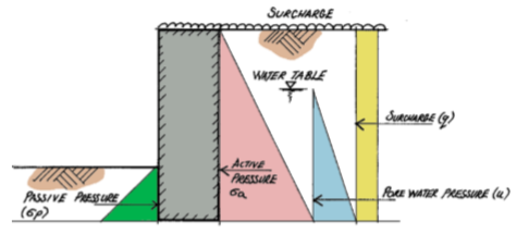
Pressure from retained materials can be broken down into three types: active pressure, passive pressure and surcharge. Active pressure is a force that has an adverse effect on the structure it is being supported by. Passive pressure is a force that counters the negative effects generated by the active pressure, and the surcharge is an applied load over and above the material that is exerting a lateral pressure to the retaining structure.
This note only considers relatively simple retaining structures for purposes of illustrating how loads originating from retained materials are derived. For more complex retaining structures
Active Earth Pressure (Ka)
In order to determine the lateral force a material will exert onto a retaining structure, an appreciation of the friction between the particles the material is made up of is needed. In terms of soils, this is defined by the soil’s cohesion (c), internal angle of friction (φ) and the interface between the retaining structure and the soil. All of these are taken care of by the coefficient of active earth pressure ka defined as
{ k }_{ a }=\frac { 1-sin\phi }{ 1+sin\phi }To determine the Active Pressure, the coefficient Ka is applied to the base density of the soil.
{ \sigma }_{ a }=\frac { { k }_{ a }{ \gamma }_{ s }h }{ 2 }{ P }_{ a }={ \sigma }_{ a }hWhere γs = Soil
At-rest Earth Pressure (Ko)
Where the wall develops no movement i.e. not allowed to rotate, such as in basement walls, the force that tries to topple the wall is determined based on the coefficient of at-rest pressure, defined as:
{ k }_{ o }=\quad 1-sin\phi To determine the At-rest Pressure, the coefficient Ko is applied to the base density of the soil.
{ \sigma }_{ o }=\frac { { k }_{ o }{ \gamma }_{ s }h }{ 2 }{ P }_{ a }={ \sigma }_{ o }h Where γs = Soil
Passive Earth Pressure (Kp)
Passive Pressure acts counter to the Active/At-rest Pressure and is therefore considered to be beneficial. It normally comes about due to the retaining structure being partially buried and thus creates a barrier that prevents the structure from sliding and/or overturning.
{ k }_{ a }=\frac { 1+sin\phi }{ 1-sin\phi }To determine the Passive Pressure, the coefficient Kp is applied to the base density of the soil. This is defined thus:
{ \sigma }_{ p }=\frac { { k }_{ p }{ \gamma }_{ s }h }{ 2 }{ P }_{ a }={ \sigma }_{ a }hWhere γ = Soil density; h = depth of soil (passive side); Kp= Coefficient of passive pressure; Pp= Force due to passive soil pressure
Surcharge (q)
Surcharge is an imposed load that is placed on top of the retained material. It is expressed as an area load, typically kN/m² or kPa and is transferred directly onto the retained structure. The active/at rest pressure coefficient Ka or Ko is applied to all surcharge forces that a retaining structure is subjected to.
{ q }_{ s }={ k }_{ a }q{ P }_{ s }={ q }_{ s }hWhere ; q= Surcharge load ; qs = horizontal pressure due to surcharge; Ps = horizontal force due to surcharge load
Pore Water Pressure (u)
The lateral pressure from pore water pressure u is determined based on the base density of water, which is 10 kN/m3. It must be determined and applied to retaining walls, where the water table is within the depth of the retained soil. The lateral pressure is defined as:
u=\frac { { k }_{ a }{ \gamma }_{ w }h }{ 2 }{ P }_{ w }=uhWhere; Ka= coefficient of active pressure; u = lateral pore pressure; Pw = horizontal load due to pore water pressure
Stability of Retaining Wall
A retaining wall must not only be sufficiently stiff so as to be able to support the forces generated from the lateral pressures, but it must also be stable, so that the forces acting do not cause the wall to topple or slide. There are three types of stability problem in a typical retaining wall, that must be verified as explained in the subsequent sections.
Stability Against Overturning
When lateral pressures are acting on the a retaining wall, the pressures act to topple the wall, to ensure stability the following expression must be verified.
{ M }_{ o }\le { M }_{ R }Where:
Overturning Moments (Mo): Overturning moments are those horizontally applied forces multiplied by their corresponding lever arms from the footing to their point of application. The primary force causing overturning is the lateral earth pressure against the wall and because it is a triangular load it moment arm will be one-third of the retained height above the bottom of the footing. If the backfill is sloped the height used to compute overturning is at a plane of the back of the footing (i.e. where the plane intersect the ground surface) Lateral pressure due to surcharge is uniformly applied to the back of the wall, therefore it point of application is 1/2 the height and the moment arm half the retained height to the bottom of the footing.
Resisting Moments (MR) : The resisting moments are the sum of the vertical loads about the front edge (Toe) of the footing. These forces include stem weight, footing weight, the weight of soil behind the wall and over footing, a surcharge if applicable and any axial loads on top of the wall. The total resisting moment is the product of the sum of all these loads and their moment arms taking about the front edge of the footing,
Stability Against Sliding
To ensure stability against sliding, the following expression must be satisfied
{ F }_{ s }\le { F }_{ R }Sliding Force (Fs) : The sliding forces are horizontally applied and consist of the lateral earth pressure, pore water pressure, and the horizontal component of any surcharge or axial load if present.
Resisting Force (FR) : The vertical loads consisting of the weight of the stem and base, weight of earth on the backfill and the resistance by the passive pressure.
Soil Bearing Pressure
Since a retaining wall is usually subjected to lateral forces, its foundation would be eccentrically loaded. And in estimating the bearing pressures, as with pad foundations one must first determine the location of the resultant. Is it within the middle third or outside? To determine this, the eccentricity must be determined. this is calculated by determining the out of balance moment which is obtained by taken moments about the centerline of the base.
The eccentricity is then defined as:
e=\frac { M }{ N }The eccentricity must be less than one-sixth of the footing width (i.e. within the middle third) for the footing to be in theoretical contact with the soil, if this is the case. The soil pressure can be computed from
p=\frac { N }{ w } \pm \frac { 6M }{ { w }^{ 2 } }If the resultant is outside the middle third the soil pressure is given as
p=\frac { N }{ 0.75w+1.5e } Where: e = eccentricity; w = width of footing; N = vertical loads; M = out of balance moment; p = bearing pressure
See: Structural Aspect of Designing Basement Walls
Sources & Citation
- CIRIA (2000) Publication C516: Modular gravity retaining walls: design guidance London: CIRIA
- CIRIA (2003) Publication C580: Embedded Retaining Walls London: CIRIA Hugh Brooks (2010): Basics of Retaining wall design (8ed)- HBA Publications.
- The Institution of Structural Engineers (2012): Derivation of loads to retaining structures- Technical guidance note (level2).
Thank you!
20mg cialis cheap – when does cialis become generic cialis canada buy online
cheap viagra online uk – mail order viagra viagra 1998
cialis uk paypal – daily cialis price buy cheap cialis from india
stromectol covid – stromectol 3 mg dosage ivermectin 4000 mcg
win real money online casino for free – real money online casinos usa slot machines
ed treatment – best ed pills non prescription erectile dysfunction cure
cheap generic prednisone – cost 50mg prednisone tablets where to buy prednisone uk
ivermectin 400 mg brands – ivermec4human.com where to buy ivermectin
best ed medication – natural pills for ed ed pills for sale
buy ventolin – ventolin 90 mcg ventolin tablet price
cytotec 200mg pills generic – buy cytotec online cytotec canada pharmacy
doxycycline 50 mg tablets price – doxycycline 150 mg price where can i get doxycycline online
neurontin 4 mg – buy levothyroxine 75 mcg levothyroxine 212 mcg
purchase sildenafil – viagra fast shipping canada
buy cheap cialis 20mg – cialis 80 mg price cialis otc us
cipla generic vardenafil – is vardenafil generic buy vardenafil 10 pills
ivermectin uk coronavirus – stromectol 12 mg cost for ivermectin 3mg
prednisone online paypal – prednisone daily use prednisone without precription
Hi! Do you use Twitter? I’d like to follow you if that would be
ok. I’m undoubtedly enjoying your blog and look forward to new posts.
cheap accutane – buy accutane online how to get accutane australia
buy amoxicillin 500 mg from canada – amoxil amoxil 500
medrol for sale – lyrica 75 lyrica cost in canada
viagra buy canada – stviag.com online pharmacy australia viagra
price of tadalafil 10mg – Cialis discount cialis 5 mg best price
ivermectin generic cream – stromectol tablet price generic stromectol for humans
prednisone coupon – buying prednisone 4mg without prescription 20mg daily prednisone