This article provides guidance on the assessment on loads applied to soil retaining structures based on the recommendations of Eurocode 7
Introduction
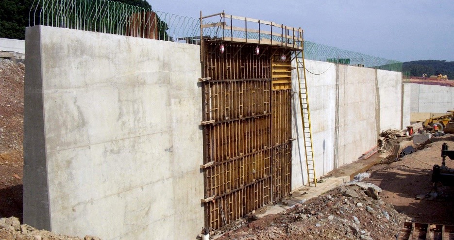
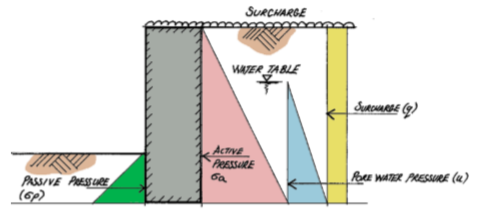
The current code of practice for the design of foundations and substructure components is Eurocode 7-1 – Geotechnical Design. When applied to substructure elements, it offers instructions on how to estimate loads from retained soil. This enables for the retaining structure to deflect when the load from the soil is applied to it and takes into account the consequences of elevated retained earth. A cross section through a retaining wall is shown in Figure 1 to illustrate the different stresses that such structures may experience.
The method by in which the forces applied by retained materials to retaining structures is fully explained in Eurocode 7-1 Clause 9.5. This clause further refers to Annex C in order to calculate these loads. According to Eurocode 7-1, a set of charts in Annex C.1 can be used to estimate the amount of loading from sources of pressure caused by retained material. The UK National Annex for Eurocode 7-1 specifies in clause N.A.3.2 that it is not advised to utilize these charts if the retaining structure has an inclined inner face because doing so would provide unsuitable results. Instead, they specify that retaining structures with inclined inner sides should be designed according to equations C6 and C9 in Eurocode 7-1.
This article would only cover relatively simple retaining structures for purposes of illustrating how loads originating from retained materials are derived. For more complex retaining structures
Derivation of Load on Retaining Walls
Pressure from retained materials can be broken down into three types: active pressure, passive pressure and surcharge. Active pressure is a force that has an adverse effect on the structure it is being supported by. Passive pressure is a force that counters the negative effects generated by the active pressure, and the surcharge is an applied load over and above the material that is exerting a lateral pressure to the retaining structure.
This note only considers relatively simple retaining structures for purposes of illustrating how loads originating from retained materials are derived. For more complex retaining structures
Active Earth Pressure (Ka)
The active lateral earth pressure is the primary force exerted by a retaining material unto a retaining structure. It is the force that tries to slide or topple a wall. In order to determine the magnitude of this lateral force, an appreciation of the friction between the particles the material is made up of is needed. In terms of soils, this is defined by the soil’s cohesion (c), internal angle of friction (φ) and the interface between the retaining structure and the soil. These parameters are obtained from a ground investigation report which must have been carried out to Eurocode 7 (part 2): Ground investigation and Testing. All of these are taken care of by the coefficient of active earth pressure ka defined as
{ k }_{ a }=\frac { 1-sin\phi }{ 1+sin\phi }To determine the Active Pressure, the coefficient Ka is applied to the base density of the soil.
{ \sigma }_{ a }=\frac { { k }_{ a }{ \gamma }_{ s }h }{ 2 }{ P }_{ a }={ \sigma }_{ a }hWhere γs = Soil
At-rest Earth Pressure (Ko)
Where the wall develops no movement i.e., not allowed to rotate, such as in basement walls, that are propped, the equivalent of the active earth pressure or the force that tries to topple the wall is determined based on the coefficient of at-rest pressure, defined as:
{ k }_{ o }=\quad 1-sin\phi To determine the At-rest Pressure, the coefficient Ko is applied to the base density of the soil.
{ \sigma }_{ o }=\frac { { k }_{ o }{ \gamma }_{ s }h }{ 2 }{ P }_{ a }={ \sigma }_{ o }hWhere γs = Soil
Passive Earth Pressure (Kp)
Passive Pressure acts counter to the Active/At-rest Pressure and is therefore considered to be beneficial. It normally comes about due to the retaining structure being partially buried, thus creating a barrier that prevents the retaining structure from sliding and/or overturning.
{ k }_{ a }=\frac { 1+sin\phi }{ 1-sin\phi }To determine the Passive Pressure, the coefficient Kp is applied to the base density of the soil. This is defined thus:
{ \sigma }_{ p }=\frac { { k }_{ p }{ \gamma }_{ s }h }{ 2 }{ P }_{ a }={ \sigma }_{ a }hWhere γ = Soil density; h = depth of soil (passive side); Kp= Coefficient of passive pressure; Pp= Force due to passive soil pressure
Surcharge (q)
Surcharge is an imposed load that is placed on top of the retained material. It is expressed as an area load, typically kN/m² or kPa and is transferred directly onto the retained structure. The active/at rest pressure coefficient Ka or Ko is applied to all surcharge forces that a retaining structure is subjected to.
{ q }_{ s }={ k }_{ a }q{ P }_{ s }={ q }_{ s }hWhere ; q= Surcharge load ; qs = horizontal pressure due to surcharge; Ps = horizontal force due to surcharge load
Pore Water Pressure (u)
The lateral pressure from pore water pressure u is determined based on the base density of water, which is 10 kN/m3. It must be determined and applied to retaining walls, where the water table is within the depth of the retained soil. The lateral pressure is defined as:
u=\frac { { k }_{ a }{ \gamma }_{ w }h }{ 2 }{ P }_{ w }=uhWhere; Ka= coefficient of active pressure; u = lateral pore pressure; Pw = horizontal load due to pore water pressure
Partial Factors for Loads on Retaining Walls
The factors that are applied to loads applied on retaining wall structures vary depending on the type of analysis being carried out. They are defined in Clause A.2 of the National Annex to BS EN 1991-1-1 and Table NA.A1.2(B) of the UK National Annex to Eurocode 0.
For instance, while checking for stability of the retaining structure with respect to overturning and sliding, it the EQU partial factors that are applied. Thus, the following partial factors are applied.
- γg – Material/Soil – 1.1 Gk when load is contributing to destabilising condition
- γg – Material/Soil – 0.9 Gk when load is acting counter to a destabilising conditionγq –
- Surcharge – 1.5 Qk when load is contributing to destabilising condition
- γq – Surcharge – 1.5 ψ0 Qk when load is contributing to destabilising condition and accompanied by another load, such as wind.
- γq – Surcharge – 0 Qk when load is acting counter to a destabilizing condition.
When designing the retaining structure (STR/ GEO), Eurocode 0 offers three approaches with respect to the application of partial factors. The UK National Annex referred to above states that Approach 1 is adopted. In this approach, two load combinations, known as ‘Sets’ are considered. These is similar to the usual partial factors applied to loads in the design of structural elements.
Worked Example
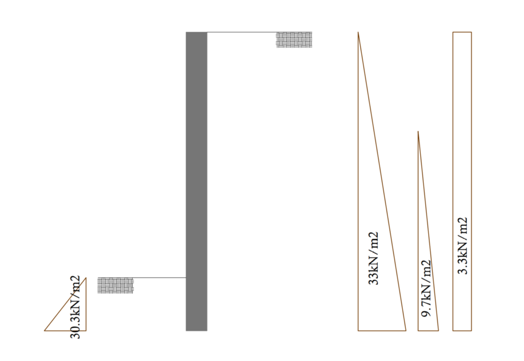
A 5m cantilever retaining wall is required as a barrier in a commercial building. The retained soil is a lateritic material with a density of 20kN/m3 and an angle of friction of 30º. A surcharge of 10kN/m2 is applied on the retaining material from movement of heavy vehicles. The front face of the wall is backfilled up to a height of 0.5m from the base. Compute the characteristic value of the total forces acting on the wall, assuming the water table is just 2.0m below the top of the retained material.
Active Earth Pressure
k_a=\frac{1-sin(\phi)}{1+sin(\phi)}k_a =\frac{1-sin(30)}{1+sin30)} =0.33{ \sigma }_{ a }= { { k }_{ a }{ \gamma }_{ s }h }= {0.33\times20\times5} =33kN/m^2Surcharge
q =k_ah =0.33\times 10 =3.33kN/m^2
Pore Water Pressure
\sigma_u= k_a\gamma_wh_o=0.33\times9.81\times(5-2)= 9.7kN/m^2
Passive Earth Pressure
k_p =\frac{1}{k_a} =\frac{1}{0.33}= 3.03\sigma_p=k_p\gamma_sh_1=3.03\times20\times0.5=30.3kN/m^2
See: Structural Aspect of Designing Basement Walls
Sources & Citation
- CIRIA (2000) Publication C516: Modular gravity retaining walls: design guidance London: CIRIA
- CIRIA (2003) Publication C580: Embedded Retaining Walls London: CIRIA Hugh Brooks (2010): Basics of Retaining wall design (8ed)- HBA Publications.
- The Institution of Structural Engineers (2012): Derivation of loads to retaining structures- Technical guidance note (level2).
Thank you!