In scenarios where traditional concrete or masonry retaining walls might be unsuitable due to ground movement or drainage considerations, gabion walls offer a viable alternative. This article offers insights into how to design gabion walls.
In the realm of civil engineering, the challenges of dealing with sloped terrains, erosion prevention, distinctively, the need for retaining walls, has led to the development of various solution. From amongst, these solutions, the gabion walls have emerged as a standout choice due to their unique combination of functionality and aesthetic appeal. These walls do not only act as support to landscapes with vast changes in elevation, but also transform the landscape into a harmonious blend of nature and engineering prowess.
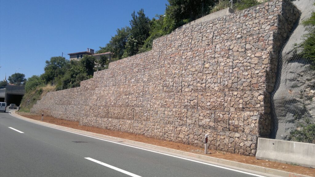
Stemming from the Italian word “gabbione,” meaning “big cage,” a gabion wall consists of wire mesh baskets or steel cages filled with rocks, stones or other sturdy materials and stacked as a unit to form a gravity wall (See featured image). They are typically constructed using 1m x 1m steel wire panels or mesh, which are unfolded at the construction site to form cages. These cages are then filled with materials, tied together and assembled into the retaining walls.
Since mesh openings are generally 75mm square holes, the rocks or infill materials are usually selected to have a nominal diameter of 75 – 200mm. Where possible, the infill material should be well graded, in order to increase the overall weight of the retaining wall.
Design Methodology
A gabion wall is essentially a gravity. This implies that when designed as retaining walls, resistance to sliding and overturning is ensured by virtue of the weight of the wall. Hence in designing a gabion wall, the units which are wired together are summed up and considered as one cohesive mass for design purposes.
In computing the lateral pressure from the soil and any surcharge applied on the backfill, it is the coulomb method of calculating the coefficient of lateral pressure that is accepted. i.e.
k_a =\frac {sin^2(\alpha+\phi)}{sin^2\alpha sin(\alpha-\delta)[1+\sqrt(\frac{sin(\phi+\delta)sin(\phi-\beta)}{sin(\alpha-\delta)sin(\phi+\beta)}]^2}Where:
- β = Angle of backfill slope
- Φ = Angle of internal friction
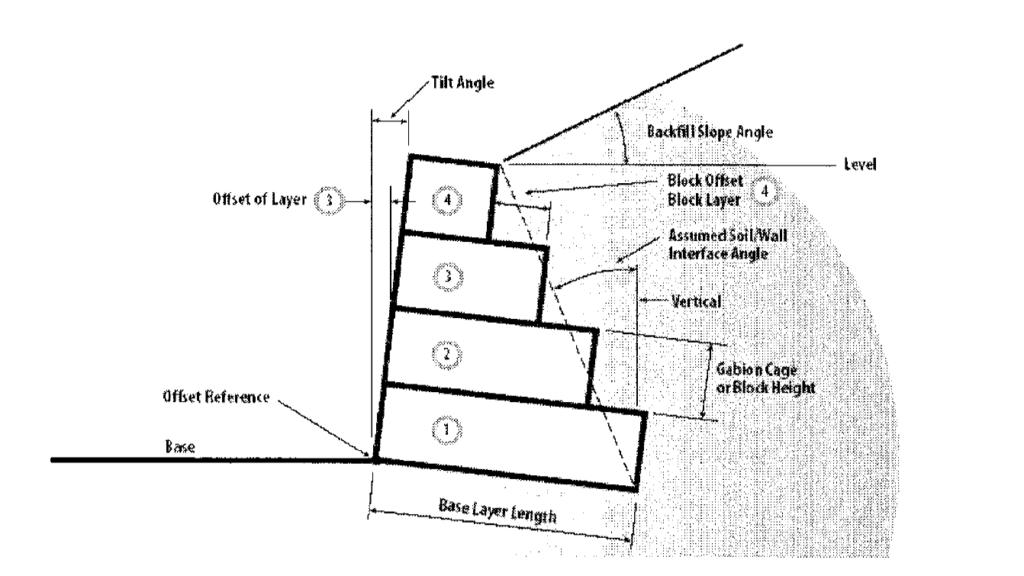
- α = 90° + (tilt angle) – (soil wall face angle as shown in figure 2)
- δ = angle of friction between soil and wall (typically 0.5-0.67Ø)
As with all types of retaining in which the stability checks include, overturning, sliding and pressure, the same checks are carried out in the design of gabion walls with minor modifications.
Sliding Resistance
The sliding resistance is the ratio of the total weight of the wall and the lateral earth pressure. Mathematically this can be expressed as:
S.R = \frac{F_R}{F_S}Where:
- FR = Resisting Force (kN)
- Fs = Sliding Force (kN)
- S.R = Sliding Resistance
To satisfy the sliding requirement S.R must be less than 1.0. In computing S.R, the partial factors applicable to favourable and unfavourable actions should be applied.
In checking for sliding, the sliding resistance is not only computed at base level but also between individual gabion units (For example, where there are 4 gabion units say, A, B, C, and D, the sliding resistance must be verified at the interface of A & B, B & C, C-D in addition to the base level.
Overturning Resistance
The overturning resistance is defined as the ratio of resisting moment and overturning moment. Mathematically, defined as:
O.R = \frac{M_R}{M_S}Where:
- MR = Resisting Moment (kN.m). Taken for each unit, as the weight of the unit multiplied by the distance from the point reference edge to the centre of gravity of the unit. (See Figure 1)
- Mo = Overturning Moment (kN.m). Taken as the lateral earth pressure multiplied by the distance from the point of application of the resultant of the pressure and the reference point.
- O.R = Overturning Resistance
Similarly, to the sliding check, the overturning resistance must be verified at the interface of each unit and the base.
Pressure Verification
Gabion walls generally do not have a concrete footing, as in other types of retaining walls. Rather they are constructed on a firm base level, often gravel.
In gravity retaining walls, the geometry of the wall must be such that it prevents any tension been generated within it. Therefore, with respect to pressure, the gabion wall geometry must be checked to ensure that eccentricity of the resultant of the pressure is within the middle third of the base.
To ensure that the eccentricity is within the middle third of the base, its value must be less than one-sixth of the width of the gabion wall at base level.
Eccentricity can be computed from:
e = \frac {w}{2} - \frac{M_R-M_O}{V}Where:
- e = eccentricity.
- w = width of gabion wall at base level
- MR = resisting moment at base level
- Mo = overturning moment at base level
- V = Total vertical load at base level
Where the resultant is within the middle third.
Having determined the position of the middle third, the soil bearing pressure is given as:
p =\frac{V}{w}\pm \frac{6Ve}{w^2}The soil bearing pressure is compared with the bearing resistance of the base and found to be satisfactory.
Steps in Designing a Gabion Wall
- Establish the retained height, and geometry of the gabion retaining wall, using a trial-and-error approach. Typically, the dimension of each unit should increase by one (1m x 1m) cage.
- Check the stability of the wall in overturning, sliding at the interface of each unit and then at the face
- Verify that the pressure at the base level is within the middle third and is less than the bearing resistance of the base.
Worked Example
A 10m tall gabion retaining wall is to be constructed to create a change in elevation between two residential buildings. The wall is to retain a granular soil that has a density of 18kN/m3. The water table has been found to be below the level of the base to the retaining wall and there is a surcharge of 10 kN/m2 applied on the backfill. The angle of shear resistance φ is 30º, the tilt angle of the wall is 5º and the coefficient of friction between the base soil and the concrete is 0.55. Size the retaining wall assuming that the bearing resistance of the base is 300kN/m2.
Solution to the worked example and is displayed in the tabs below.
Also find below; the TEDDS FOR WORD Document used to produce the calculations below.
Also See: Retaining Walls Construction Methods
Sources & Citations
- Brookes H. (2010) Basics of Retaining Wall Design – a guide for the practicing engineer (8th Ed) CA. USA HBA publications Inc.