In the design of trusses, timber is another alternative that should be considered at the preliminary design stage. When dealing with a small-moderate span, timber trusses are largely economical and the expertise required for fabrication is far less relative to steel solutions. However, this is only the case when spanning requirement are at least moderate. With large spans, a timber truss become grossly uneconomical, the economic benefits wean ‘off due to the size of timber sections that is required to satisfy design requirements.
The design and detailing of timber trusses is often considered a specialist field and is mostly left to the contractor or fabricator onsite. Thus, it is a design item that falls outside the main responsibility of the structural engineer. Even though, trusses are to conform to the design criteria of the building for which they will be install into, the sizing of the components as well as their fabrication is left to the contractor. However, since a structural engineer retains the responsibility for the overall stability of a structure, it’s pertinent that the structural engineer understands the theory behind the design for the purpose of assessing designs produced by these contractors.
The focus of this article is on the design and detailing of timber trusses. It has been developed to equip the structural engineer with sufficient knowledge to appraise the design of timber trusses. Its scope is however limited to member design, the different types of stresses they may be subjected to and the detailing considerations. The scope does not cover the design of the connections, even though connections could govern the design of the elements as would be reflected later in the article.
The design of timber trusses is a very complex subject, hence the advice given in this article are not to be treated as exhaustive, it should be treated as a guide. Readers are strongly encouraged to consider consulting the reference texts in the “sources & citation” section of this article.
Forms of Timber Truss
Timber trusses can assume a variety of forms; however, they can be summarized into three distinct categories: These are:
- Simple
- Complex
- Hybrid
Simple Truss
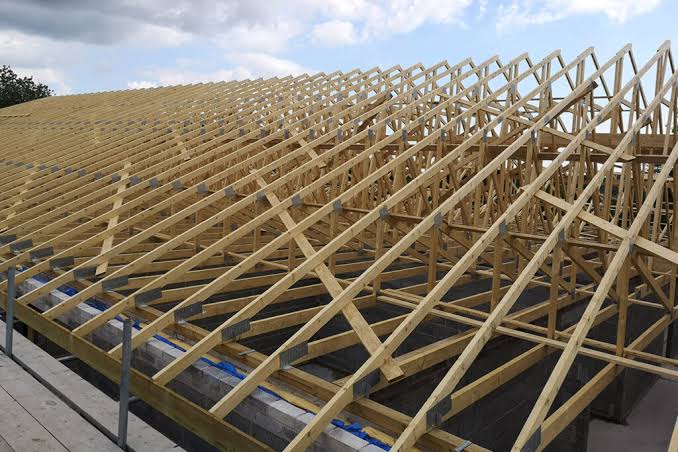
Simple trusses (Figure 1) are assembled from monolithic timber elements, with punched metal plate fasteners acting as connections between each element within the truss. They are usually designed as secondary elements and support mainly finishes. They consist of a slope of 15–40° and are used where the maximum span doesn’t exceed 15m. The depth of the top chord is typically sized using a span/75 to span/100.
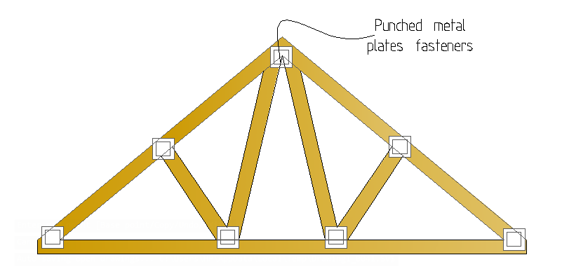
In designing a simple truss, the engineer must consider thoroughly, the effect of buckling. Because the effect of negative pressure, for example, from wind on a roof is that it leads to stress reversals, causing the top chord to be in tension whilst the bottom chord is in compression. Hence, sufficient restraints must be provided to the top and bottom chords to avoid buckling. These restraints are provided by bracing elements fixed within the rafter and ceiling spaces of the roof structure.
Complex Truss
Complex trusses (Figure 2) on the other hand are constructed from monolithic or composite timber materials such as glued laminated timber (glulam) or laminated veneer lumber (LVL). In contrasts to simple trusses, they are primary elements supporting roof purlins within roof structures. Their connections are usually bolted. Restraints to the trusses is usually provided through the use of the large purlins on the top chords of the truss, while ceiling tiles are used to restraint the bottom chord.
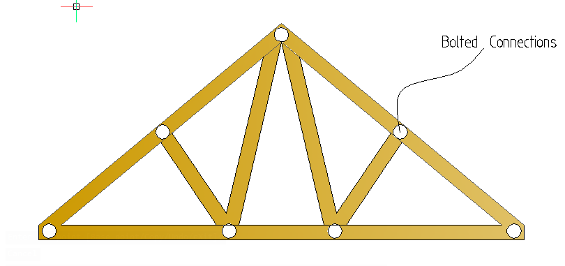
Complex trusses can span up to 20m. They typically have a slope of 15–45° and the depth of the top chord is typically sized using span/60 to span/80.
Hybrid Truss
A hybrid truss (Figure 3) is a mix of steel and timber sections. The timber sections can be glued laminated timber or laminated veneer lumber, used to make the top chord to act as compression members within the truss assembly. While all other elements are made of steel and are fixed to the timber using bolted connections.
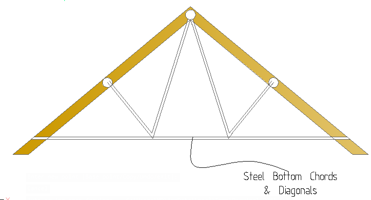
Hybrid trusses can span up to 80m and they have a slope of at least 14°. The depth of their top chord is sized using a span/40 ratio.
Detailing a Timber Truss
Before carrying out a detailed design, there are certain areas of interest in the detailing of a timber truss components that must be understood. This will be explained in the following headings.
Lateral Stability
Timber trusses in their typical forms are inherently unstable, their lateral stability is being derived from the use of bracing systems. These bracing when provided must act by diaphragm action with the roof structure they restrain. The restraints must be able to brace both the top and bottom chords since it’s typical for roofs to be subjected to both positive and negative wind pressures.
As a rule, and for the purpose of elements sizing and detailing, the maximum distance between trusses within a roof structure should be limited to 1200mm. Where it is required for the trusses to be placed at greater centres, bracings should be provided in plan and in the plane of the top and bottom chords of the truss. These bracings are usually made of isolated timber elements, acting as struts, fixed unto the trusses and acting as primary components of the lateral stability system.
Ultimately, lateral stability of a timber roof is a special area of interest for the structural engineer and he must ensure that it is always properly addressed.
Tying
Tying is another important consideration for the structural engineer. When compared to concrete and steel, timber is a relatively lightweight material. Hence, a timber truss being part of the roof of buildings will need to be tied down to the structure, else the risk of uplift due to negative pressure from wind or suction at the ends of gables. Both uplift and suction can cause the roof to ultimately decouple and then cause failure.
The structural engineer must ensure that the truss designer, prior to fitting the truss has considered uplift and provided the holding down detail, ensuring that uplift action is being sufficiently resisted. In addition, it is possible to restrain the perimeter walls to roof trusses. The gable walls will require significant number of lateral restraints, as they reach the apex of the roof structure due to the magnitude of uplift in the region.
Similarly, the tendency of the roof to spread and sliding should be assessed and reviewed by the structural engineer. Most times, they’re resisted by the positive connection between the roof and the structure
Designing a Timber Truss
The components of a timber truss can be described with reference to more simple elements most of which have being addressed in previous articles. The design of a timber truss should cover:
- Design of a compression member
- Design of a Tension member
- Design of a member in combined tension/compression and bending.
For simple trusses it’s easier to simplify the process to the design for compression and tension only. This is based on the assumption that the members in the truss are pin-jointed and the loads are beings applied at the nodes only, so that the forces induced in the members are solely either compressive or tensile. Simplification of the design can always be achieved by proper detailing of the truss connections. However, where the loads are applied on the rafters, or for some other reasons bending is induced in the truss members, they must now be assessed for combined action. This is beyond the scope of this article; however, guidance may be obtained from the texts listed at the end of this article.
Design for Compression
The design of timber element against compression has being covered in previous article (See: Design of Timber Posts to EC5). To design against compression, the following equation must be verified:
{ \sigma }_{ c,0,d }\le { f }_{ c,0,d }Where:
- σc,0,d is the applied compressive stress
- fc,0,d is the design compressive resistance
{ \sigma }_{ c,0,d }=\frac { { N }_{ Ed,c } }{ A }\quad { f }_{ c,0,d }=\frac { { k }_{ sys }{ k }_{ c }{ k }_{ mod } }{ { \gamma }_{ M } } { f }_{ c,0,k }Where:
- NEd,c is the design compressive force
- A is area of timber section:
- fc,0,k is the characteristic compressive strength (N/mm2). See Table 1 for values.
- γM is the material partial factor of safety taken as 1.3 in the case of solid timber
- kc, ksys and kmod are coefficients relating to instability, load duration and exposure condition respectively. Their values are defined in N.A- BS EN 1995-1-1.
Design for Tension
To design against tension in timber, the following equation must be verified:
{ \sigma }_{ t,0,d }\le { f }_{ t,0,d }Where:
- σt,0,d is the applied tensile stress
- ft,0, d is the design tensile resistance
{ \sigma }_{ t,0,d }=\frac { { N }_{ Ed,c } }{ A } ;\quad { f }_{ t,0,d }=\frac { { k }_{ sys }{ k }_{ c }{ k }_{ mod } }{ { \gamma }_{ M } } { f }_{ c,0,k }Where:
- NEd,t is the design tensile force
- A is area of timber section:
- ft,0,k is the characteristic tensile strength (N/mm2). See Table 1 for values.
- γM is the material partial factor of safety taken as 1.3 in the case of solid timber
- kc, ksys and kmod are as defined earlier while kh relates to the depth of the timber section. Its value is defined in the N.A to BS EN 1995-1-1.
| Grade | C16 | C24 |
| Compression Parallel to the grain(fc,0,k) (N/mm2) | 7.2 | 8.5 |
| Tension Parallel to the grain (ft,0,k) (N/mm2) | 17 | 21 |
Worked Example
The figure shown below is a section of a mono-pitch roof over the gallery of large church auditorium. In other to provide a large uninterrupted space, the use of timber trusses is being considered as an alternative to the use of steel sections. Produce sufficient calculation to establish the forms and sizes of the timber elements using C24 timber.
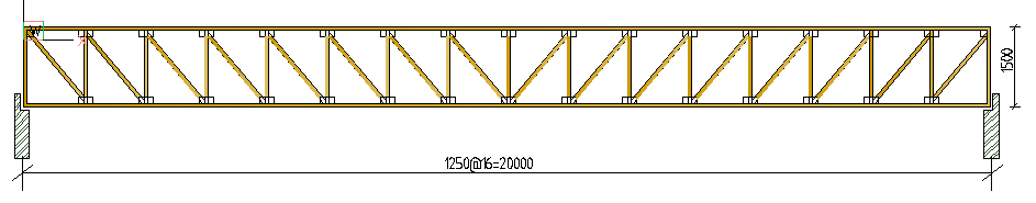
This was the exact worked example presented in the article “Design of Steel Trusses to EC3.” The analysis of this truss has been carried out and the results obtained. Hence in this article, only the design of the members is presented.
Sources & Citations
- Institution of Structural Engineers and TRADA (2019) Manual for the design of timber building structures to Eurocode 5 (2nd ed.), London/ High Wycombe: IstructE Ltd/TRADA
- O’Regan C. (2017) ‘Technical Guidance Note (Level 2, No. 23): Design of triangular trusses, The Structural Engineer, 98 (11), pp. 20–23
Thank You!!!