When an adjacent footing overlay the area of the soil wedge of a retaining structure, the footing exerts a lateral surcharge pressure against the retaining wall, which must be considered in the analysis and design of the retaining structure.
In the analysis and design of retaining structures, several lateral forces come into play. These forces can be principally broken down into three types: Active, passive and surcharge pressure. The active pressure is that force that is averse to the retaining wall structure, primarily due to backfill it supports, while the passive pressure is the force that tries to counteract the active pressure. Surcharge pressure can be classified as any loads that exerts an additional pressure on the backfill, thereby causing more aversity for the retaining structure.
Deriving the active and passive pressures is pretty easy and requires the active and passive pressure coefficient to be applied to the base density of the back fill/front fill as the case may be. Also, where the surcharge is uniform over the backfill, such as in consideration of roadways, construction activities and moving vehicles, the lateral force due to the surcharge can simply be estimated by applying the coefficient of lateral pressure to the surcharge.
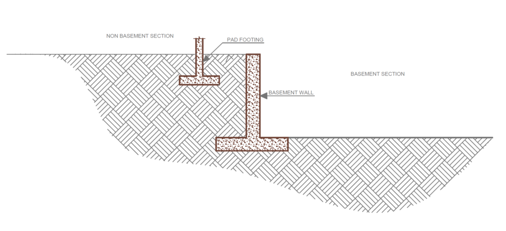
However, a unique problem that often requires a unique solution arises when a surcharge arises from an adjacent footing that overlays the area of the soil wedge, this surcharge exerts a lateral pressure against the retaining wall, hence must be considered. A common example of this design challenge occurs in buildings that has a basement level, but the basement level doesn’t cover the entire footprint of the building. A retaining wall is often provided at the interface of the section consisting of the basement and the section without the basement. The implication is that the foundation of the section without the basement will exert a pressure against the wall, therefore the magnitude of this pressure must be estimated, and the wall designed to resist it (Figure 1).
This does not however, imply that all footing on the section without basement will exert a force on the wall. The farther the footing is away from the wall, the smaller is its effect on the wall becomes and may even be ignored. Thus, a rule-of-thumb is that an adjacent footing will have little effect on lateral pressure against the stem if it is further than the height (base of stem to base of applied adjacent load) away from the wall face – at a slope ratio of 1: 12.
How to derive active, passive and even pressures from simple surcharges has been covered in a previous article (See Derivation of Loading to Retaining Structures). The focus of this article is how to estimate the lateral pressure exerted by an adjacent pad/strip footing on a retaining wall.
Surcharge Pressure from Footings
In other to compute stresses at any point in a soil mass, the theory of elasticity is often employed. Several equations have been developed to compute these stresses based on this theory which also applies to lateral pressures from surcharges from adjacent footings in the form of “line,” or “strip” loads on unyielding retaining walls.
Line Loads
The theory of elasticity states that the stress on a retaining structure induced by a line load of intensity q/unit length at any depth, z, may be expressed as follows:
\sigma =\frac{2q}{\pi H} \frac{a^2b}{(a^2+b^2)^2}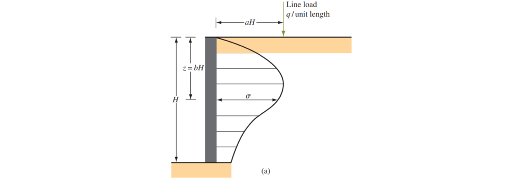
Where: σ = horizontal stress at a depth; z = bH. (See Figure 2 for explanations of the terms and b.)
However, it must be stated that soil is not a perfect elastic material. In fact, the entire basis of applying the theory of elasticity is that it’s expected that stresses within the soil mass are relatively small. Hence, in view of this, some deviations from the equations above is anticipated. These modified equations used to compute the horizontal stresses is depended on the width of the strip loading a and the equations are written below:
Where a > 0.4
\sigma =\frac{4q}{\pi H} \frac{a^2b}{(a^2+b^2)^2}Where a <= 0.4
\sigma =\frac{q}{ H} \frac{0.203b}{(0.16+b^2)^2}Strip Load
Where the load is a strip loading with an intensity of q(kN/m2) as show in in figure 3. Based on the theory of elasticity, the horizontal stress σ due to a footing, at any depth z on a retaining structure can be computed as:
\sigma =\frac{q}{\pi}(\beta-sin\beta cos2\alpha)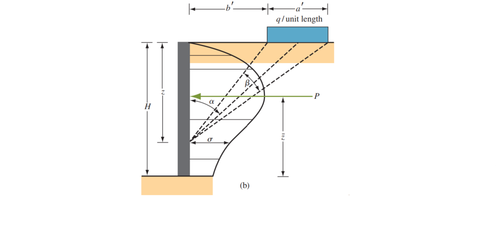
The angles β and α are defined in Figure 3
However, in the case of soil, the right-hand side of the above equation must be doubled to account for the yielding soil continuum. This can be expressed as:
\sigma =\frac{2q}{\pi}(\beta-sin\beta cos2\alpha)The above equations have dealt with the pressure distribution on a retaining structure at given depths due to strip loading from adjacent footings. However, in the derivation of loading on retaining structures, it may be beneficial to just derive the resultant horizontal force and the lever arm as this is what is actually required to derive the contribution of the surcharge to stability and design resistances.
The total horizontal force per unit length (P) due to the strip loading only (Jarquio, 1981) may be expressed as:
P =\frac{q}{90}[H(\theta_2-\theta_1)]Where:
\theta_1=tan^{-1}(\frac{b'}{H})\theta_2=tan^{-1}(\frac{a'+b'}{H})The lever arm z of the resultant force, P, can be given as:
z=H-[\frac{H^2(\theta_2-\theta_1 + (R-Q)-57a'H}{2H(\theta_2-\theta_1)}]where:
R=(a'+b')^2(90-\theta_2)
Q=b^{'2}(90-\theta_1)Worked Example
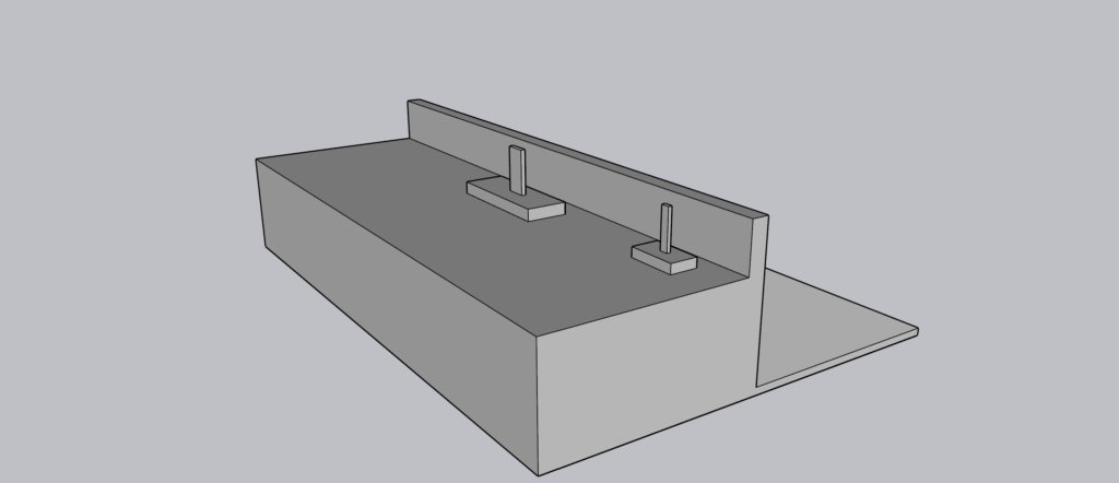
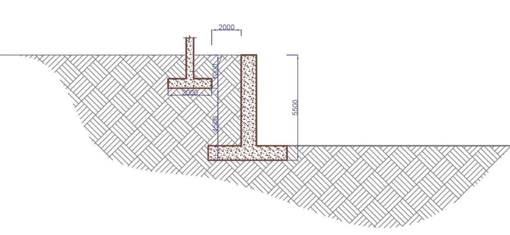
Figure 4 shows a 2m x 2m pad footing located at 1m depth below ground level and 2m away from a proposed 5.5m deep basement wall. Assuming the surcharge from the pad footing is 175kN/m2, Estimate the resultant lateral force surcharge on the basement wall and its lever arm.
Resultant Lateral Force
Although the basement wall is 5.5m Tall. The height of the basement used for computation is 4.5m because the surcharge load is located 1m below existing ground level.
a'=2m
b' = 2m
\theta_1=tan^{-1}(\frac{b'}{H})\theta_1=tan^{-1}(\frac{2}{4.5}) =23.96\deg\theta_2=tan^{-1}(\frac{a'+b'}{H})\theta_2=tan^{-1}(\frac{2+2}{4.5}) = 41.63\degP =\frac{q}{90}[H(\theta_2-\theta_1)] P =\frac{175}{90}[4.5(41.63-23.96)] =154.6kN/mResultant Lateral Force
R=(a'+b')^2(90-\theta_2)\\=(2+2)^2(90-41.6)=774.4
Q=b^{'2}(90-\theta_1) =\\ 2^2(90-23.96)=264.2z=H-[\frac{H^2(\theta_2-\theta_1 + (R-Q)-57a'H}{2H(\theta_2-\theta_1)}]\\ =2.21mIn the analysis and design of this basement wall, this resultant lateral force (154.6kN/m) must be considered to act alongside with the active, passive, pore, and other surcharge pressures at a distance of 2.21m from the base.
Also see: Designing a Counterfort Retaining Wall | Worked Example
Sources & Citation
- B.M Das and N. Sivakugan (2019). Principle of Foundation Design. Ninth Edition, SI Edition
- Brookes H. (2010) Basics of Retaining Wall Design – a guide for the practicing engineer (8th Ed) CA. USA HBA publications Inc