This fifth installment on the series on concrete bridges provides insights on the maintenance and management of concrete bridges.

Previous articles provided insights on topics such as the resilience of concrete bridges, selecting a Concrete bridge layout, strategies for reducing bearings and joints, and the integration of integral bridges, the critical aspects that underpin the enduring functionality of concrete bridges structures. Central to this endeavor is the meticulous consideration of bridge concrete specifications, encompassing crucial elements like strength, reinforcement parameters, water-to-cement ratios, and the selection of appropriate cement types. These specifications are meticulously tailored to suit the unique demands of each site and the prevailing environmental conditions, serving as the foundation for ensuring the optimal performance and longevity of concrete bridges.
Adherence to these crafted specifications not only guarantees structural robustness of concrete bridges but also plays a pivotal role in mitigating maintenance requirements and prolonging their operational lifespan. As we navigate through this discourse, our attention turns towards the integral practices of bridge inspection and maintenance, essential components in the ongoing stewardship of these critical transportation arteries. Furthermore, we explore potential strategies for strengthening concrete bridges to accommodate evolving load configurations or revised layout designs, ensuring that they remain resilient and adaptable to the ever-changing demands of modern infrastructure.
Deterioration mechanisms
Despite concrete’s reputation for durability, stemming from its inherent hardness and centuries-long history dating back to the Roman era, it remains susceptible to deterioration influenced by local environmental conditions. Concrete, being inherently alkaline, creates a protective environment for steel reinforcement by forming a passivating film on its surface. However, this protective film can diminish due to external factors like the infiltration of atmospheric gases or chloride ions from sources such as de-icing salts or seawater. The rate at which this degradation occurs hinges upon various concrete properties, including its water-to-cement ratio, permeability, and electrical resistance. Under certain circumstances, these variables can precipitate the onset of corrosion in the steel reinforcement.
The main deterioration mechanisms impacting concrete structures are outlined below. Each is elaborated on separately, detailing their respective maintenance needs.
- carbonation
- chloride ingress
- sulphate attack
- corrosion of reinforcement
- alkali-silica reaction
- freeze-thaw cycle
- impact
Secondary problems, such as thermal, bacterial and radiation damage, are unlikely on concrete bridge structures. The principal deterioration mechanisms, and preventive/repair techniques used to address them, are described in the following sections.
Carbonation
Carbonation, a gradual reaction process initiated by atmospheric carbon dioxide, commences at the concrete surface and gradually penetrates inward. This phenomenon reduces the concrete’s alkalinity, thereby diminishing its resistance to steel corrosion. Detecting carbonation involves the application of phenolphthalein to the concrete surface, with a violet color indicating its alkalinity. It’s advisable to apply this indicator to freshly broken concrete to assess the depth of carbonation. With the potential for increased atmospheric carbon dioxide due to climate change, heightened carbonation may pose future challenges.
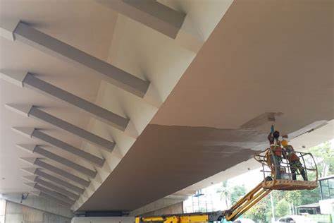
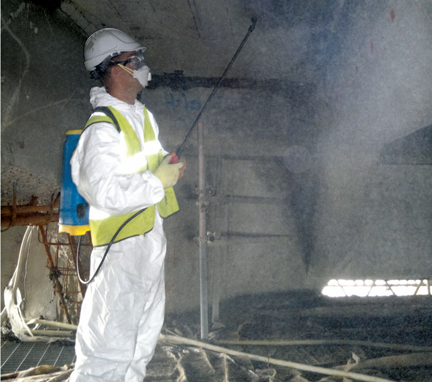
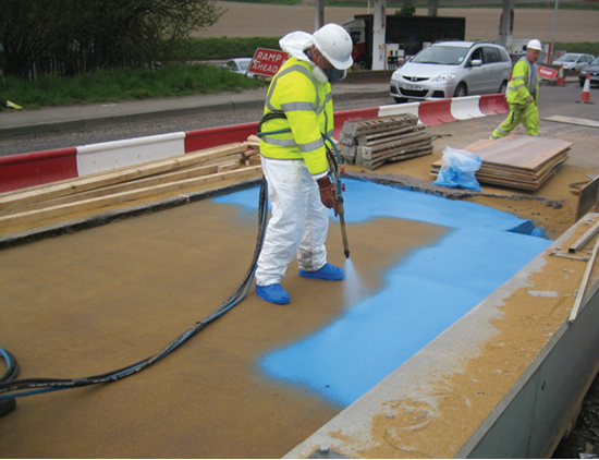
To counteract carbonation, anti-carbonation coatings offer a solution, applied through spraying or brushing to form a protective barrier (see Figure 1). Maintenance of these coatings should be integral to the bridge maintenance plan. Additionally, the installation of migrating corrosion inhibitors (MCIs) proves effective. These inhibit electrochemical corrosion reactions on reinforcing bars’ surfaces and are typically applied by brushing or spraying onto the concrete (see Figure 2). Due to their migrating properties, MCIs penetrate the concrete, safeguarding steel reinforcement from chloride attack. Alternatively, tablet-form MCIs can be inserted into regularly spaced drilled holes in the concrete.
Chloride ingress
Chloride ingress primarily stems from the use of de-icing salts, though marine environments also contribute. Historically, chloride-based additives were incorporated into concrete mixes for accelerated curing, but their use in bridges was banned in the early 1970s. High traffic speeds and volumes exacerbate issues, with chloride-laden spray impacting bridge piers and deck soffits. Neglected maintenance of movement joints allows chloride-rich rainwater to seep into deck ends and bearing shelves.
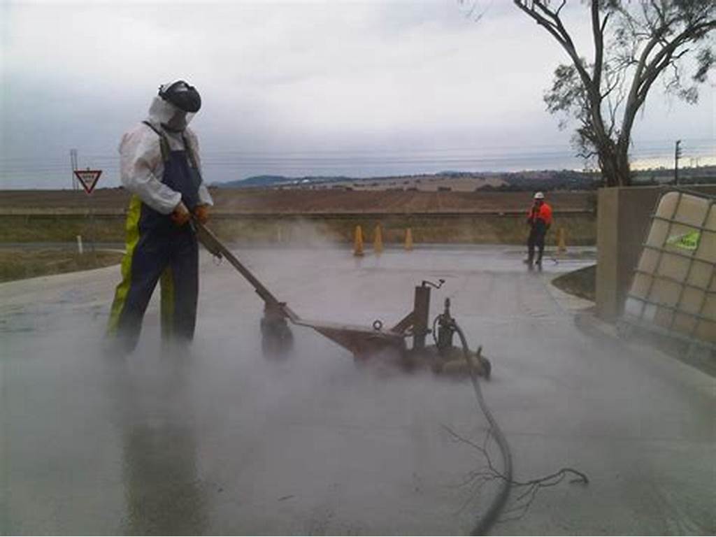
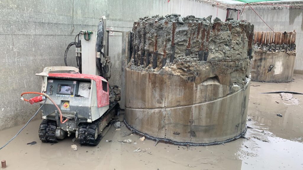
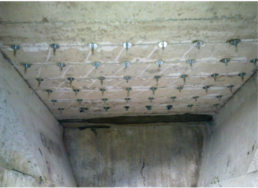
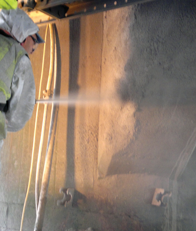
Chloride ions permeate concrete pores, attacking the passive film shielding steel reinforcement, leading to corrosion. Rust, a corrosion byproduct, expands, causing concrete cover delamination and spalling, exposing reinforcement and necessitating repairs. The extent of repair depends on chloride contamination and reinforcement condition. Chloride-contaminated concrete often requires hydro-demolition for removal, minimizing damage to retained concrete and reinforcement (Figure 3). Reinforcement replacement or supplementation may be necessary based on section loss and structural capacity (Figure 4).
Eradicating embedded chlorides necessitates removing concrete behind reinforcement bars to ensure proper adhesion of new concrete. Careful application, whether spraying, pouring, or hand-placing, is crucial to avoid void formation. Eliminating chloride sources, such as replacing bearing shelves and movement joints, is vital. Deck waterproofing, mandatory for new UK bridge decks, prevents chloride ingress. Additionally, applying a red sand carpet over the waterproofing membrane alerts future surfacing operations to its presence, enhancing safety and efficacy (see Figure 5).
Sulphate Attack
Sulphate attack commonly occurs in buried structures with groundwater high in sulphates, particularly in clay soils or due to other sources like gypsum. This attack alters the concrete’s molecular structure, forming ettringite within the cement paste. The concrete takes on a sandy appearance and becomes easily removable with handheld tools.
In specific wet conditions in clay soil, a type of sulphate attack gradually replaces the cement paste matrix with Thomasite mineral. Repair often necessitates complete replacement, as reversal is not feasible. For reconstruction, BRE publications offer cement content recommendations based on sulphate concentration, with sulphate-resisting cement available. Buried structures typically receive a coat of bituminous waterproofing before backfilling to enhance resistance.
Corrosion of Reinforcement
The corrosion of reinforcement in concrete structures can occur due to various factors, including insufficient cover to the steel. In recent years, cathodic protection (CP) has become increasingly utilized to prevent further corrosion, particularly in chloride-contaminated concrete. This method allows sound concrete to remain in place, minimizing the need for extensive removal and replacement. There are two primary types of CP systems used in bridges: sacrificial anode and impressed current. The choice between them depends on factors such as the structure’s condition, budget, and expected post-repair lifespan. Sacrificial anodes, introduced in the 1990s, function by corroding preferentially to the steel they protect. These anodes, typically containing zinc or aluminum cores, are placed around repairs to shield steel in adjacent chloride-contaminated concrete. The simplicity of sacrificial anode systems makes them an attractive option for bridge owners, as they require minimal long-term maintenance. Another development is the hybrid anode system, which initially employs impressed current treatment followed by long-term sacrificial anode protection. This system offers a straightforward solution to corrosion issues and eliminates the need for a permanent power supply.
In contrast, impressed current CP derives its electricity from a DC power supply, offering uniform protection levels regardless of operating conditions. It is suitable for environments with high chloride concentration, carbonated concrete, and where an extended design life is needed. Impressed current CP systems typically utilize inert anode materials, such as titanium, connected to the positive pole of a DC power supply unit, with the structure serving as the cathode. These systems require performance monitoring to ensure adequate protection, often using half-cell reference electrodes to measure the influence of CP on reinforcement potential. CP systems are often designed with multiple independent anode zones to accommodate variations in concrete conditions, with bespoke power supply units incorporating data-logging equipment and telemetry for monitoring performance.
Alkali-silica Reaction
The alkali-silica reaction arises from the interaction between hydroxyl ions in the alkaline cement pore solution and reactive silica forms in the aggregate, such as chert, quartzite, opal, and strained quartz crystals. This reaction produces a gel substance that expands, causing concrete cracking; often, the gel seeps out from the crack. The issue commonly manifests where water contacts surfaces, like joints, upstands, plinths, and drip features. In unrestrained concrete, the reaction results in characteristic ‘map cracking’ or ‘Isle of Man cracking’. If the concrete remains dry, the reaction may not occur. In cases of minor or non-structural damage, sealing cracks and halting water ingress may stabilize the situation.
However, severe damage necessitates demolition and replacement. Current specifications restrict the alkali content in cements used with aggregates containing reactive silica to prevent such issues in new concrete.
Freeze-thaw Cycle
Freeze-thaw cycle damage occurs when water enters the concrete matrix and expands upon freezing, potentially causing cracks. Upon thawing, the cracked concrete spalls. This process is ongoing, with higher concrete strength generally offering greater resistance. In the late 1970s, air entraining gained popularity. An admixture introduces air bubbles during mixing (typically 0.4mm diameter), which disrupt the capillary action of concrete hydration pores (typically 0.025mm diameter), preventing water absorption. Repairing frost-damaged surfaces typically entails removing and replacing the affected material.
Impact
Impact damage often results in severe consequences due to the energy transmitted and its dispersion throughout the structure, potentially compromising structural integrity and posing an immediate risk of collapse. Despite the severity, repairs typically target localized areas. Attention must be directed towards assessing the impact on reinforcement or prestressing tendons, if present, as they could sustain damage. The procedure involves removing any loose material, inspecting reinforcement and tendons, and ensuring structural capacity before applying suitable cementitious repair materials.
Edge beams are particularly vulnerable to impact damage, posing challenges in redistributing loads. When the majority of the structure remains sound, various repair techniques are viable, applicable not only to damage but also deterioration in general. Percussive methods or hydro-demolition can remove affected concrete, while resin injection effectively seals cracks (Figure 6). Exposed reinforcement undergoes assessment for area loss, with options to retain or replace it. New concrete can be cast in place or sprayed onto the affected areas. Subsequent treatments, as discussed earlier, are then implemented as needed (See Figure 7).
Bridge Investigation
Bridge owners typically conduct regular principal inspections, and if issues are identified, it’s advisable to conduct a detailed investigation of the cause and/or a comprehensive condition survey. While risk-based assessments can potentially adjust inspection intervals, this is not yet widespread practice. Investigations involve conducting checks to assess the extent and impact of potential issues described earlier.
- detailed visual survey
- carbonation analysis
- chloride content analysis
- sulphate content analysis
- cement content analysis
- reinforcement cover survey
- half-cell potential survey
- visual check
A comprehensive visual survey meticulously documents all structural defects, pinpointing areas for subsequent investigations, including ancillary components like bearings, parapets, fixings, and joints.
On-site assessment of carbonation depth involves applying phenolphthalein to freshly broken concrete surfaces. Chloride content evaluation entails drilling into the concrete to collect dust samples for analysis, noting the depths of extraction. Sulphate content analysis is conducted in a laboratory using samples obtained from the site. Cement content determination, crucial for meaningful chloride and sulphate assessments, is derived from on-site concrete samples, offering insights into the original concrete quality.
Reinforcement cover surveys are typically conducted once in a structure’s lifetime, utilizing electromagnetic cover meters. However, data accuracy is enhanced by locally exposing reinforcement through breakout, often combined with necessary breakouts for electrical connections in half-cell potential surveys. This technique gauges the likelihood of reinforcement corrosion by comparing the electrode potential of steel bars to a reference electrode’s known potential (usually copper/copper sulphate or silver/silver chloride). The survey involves connecting to the reinforcement and taking surface measurements on the concrete.
Conclusion
Concrete is an ideal structural material for use in bridges. It is relatively easy to handle, mix and place, and offers a robust form of construction, partially due to its mass. A concrete structure should perform for its minimum design life of 120 years without significant problems, providing attention is given to its environment and use, good detailing is applied, the right constituents, finishes and reinforcement cover are selected, and it undergoes routine maintenance of drainage and joints. However, it is the responsibility of the asset owner to ensure maintenance is carried out to limit the ingress of water and deleterious materials arising from blocked drainage or leaking joints. A responsible owner will keep these issues under control with a maintenance regime that will keep the bridge functioning as it was intended.
Also See: Construction of Concrete Bridges: Selecting a Bridge Layout
Sources & Citation
- Concrete Bridge Development Group (2014) ‘Concrete Bridge Design and Construction series No. 12: Management of Concrete Bridges’, The Structural Engineer, 92 (11), pp. 40–45
- Construction (2nd ed.), London, UK: ICE Publishing Concrete Bridge Development Group (In press) Technical Guide No. 14: Best Construction Methods for Concrete Bridge Decks, Camberley, UK: CBDG