This article explores the structural analysis and design of Corbels based on the guidance and recommendation of Eurocode 2 (part 1)

Corbels have long been an integral part of architectural design, dating back to ancient civilizations where they served both functional and decorative purposes. These structural elements, often made of stone, wood, or metal, project from a wall to support heavy loads such as beams, or even statues. Today, corbels are designed as structural elements and used to support heavy loads, often found in buildings, bridges, and other infrastructure.
Within the context of structural engineering, a corbel can be idealized as cantilever, albeit a short cantilever. However, there is stark difference between a corbel and a traditional cantilever. While a cantilever is resisting bending moment and shear force along its length, a corbel is usually too short, hence the transfer of forces is through a combination of axial forces.
Eurocode 2 (EN 1992-1) Design of Concrete Structures provides a comprehensive guideline for the design of concrete structures, including corbels. This article provides a comprehensive analysis of the key principles and design considerations involved in designing corbels to the above-referenced code.
Designing a Corbel
In reinforced concrete design, concrete can withstand compressive stresses, while steel reinforcement can withstand tensile stresses. This concept is typically represented by concrete struts and steel ties, forming the core principle of the strut-and-tie design method. This method is applicable in designing various structures such as pile caps, deep beams, corbels, half-joints, and more structures. In specific scenarios, Eurocode 2 allows the utilization of the strut and tie method to analyze and design corbels. As stated in clause 6.5.1 of EN 1992-1-1:2004, this method is applicable in situations where there is a nonlinear stress distribution, such as near supports, concentrated loads, or areas experiencing plain stress.
This article will not delve into the core principle underlying the strut and tie design as a whole but would touch on it as it relates to the design of a corbel.
A corbel, as shown in Figure 1 is considered to be a short cantilever when ac < z where z is the lever arm and ac are the distance from the face of the column to the bearing of the vertical force, FEd.
When the vertical load has a stiff bearing ac may be measured to the edge of the bearing but where a flexible bearing is used ac is measured to the vertical force.
Strut & Tie Analogy for Corbels
The analysis of a corbel using the strut and tie method is illustrated in figure 1. In the figure the vertical load FEd at point B is resisted by the force Fcd in the inclined concrete strut CB and the force Ftd in the horizontal steel tie AB.
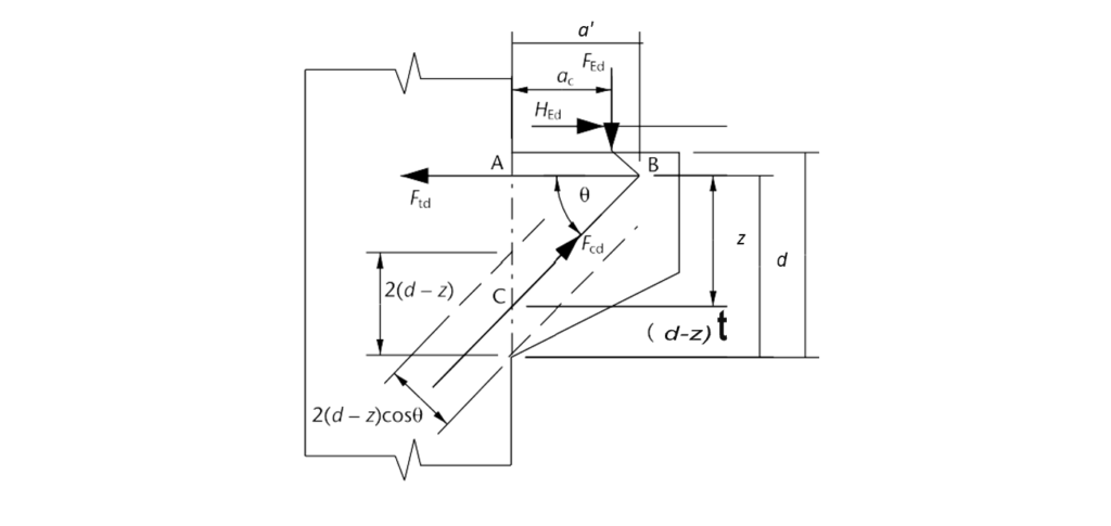
Also, Figure 1 illustrates the corbel featuring an inclined strut BC at an angle θ to the horizontal tie AB. The strut carries force FEd, while Ftd represents the force in the horizontal tie. Point B, situated at a distance a’ = (ae + 0.2aH) from the column face due to the horizontal force, HEd (= 0.2FEd).
From the triangle ABC’s geometry, the lever-arm depth is
z = (ae + 0.2aH) tan θ
a) Concrete strut force, Fcd
The design stress for the concrete strut, fed, is calculated as 0.34fck(1- fck/250). The vertical measurement of the concrete strut’s width is 2(d – z) from figure 1, with the width measured perpendicular to its axis given by Wstrut = 2(d – z) cos θ. Thus, the force FEd in the concrete strut is:
F_{Ed} = f_{cd} × W_{strut} × b_w= f_{cd} × 2(d - z) × b_w cos θWhere: bw represents the width of the corbel.
(b) Inclination angle, θ, of the concrete strut
From figure 1, resolving vertically at point B, we have:
F_{Ed} = f_{cd} sin θ \\= f_{cd}× 2(d - z) × b_w × cos θ × sin θ=f_{cd} \times d \times b_w (1-[\frac{a'}{a}]tan \theta)sin2\thetaIf we rearrange the above equation, we have:
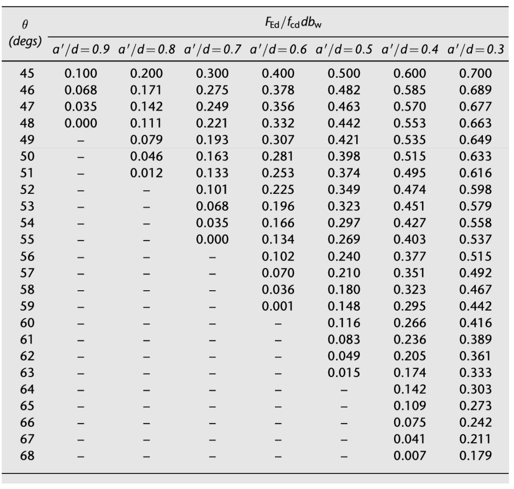
\frac{F_{Ed}}{f_{cd}db_w} =(1-[\frac{a'}{d}]tan \theta)sin2 \thetaThe above equation cannot be directly solved for θ, but Figure 2 (overleaf), derived from the above equation can be utilized for design purposes.
(c) Main tension steel, As,main
Resolving horizontally at B, the force Ftd in the steel tie is:
F_{td} = F_{Ed} cos θ = F_{Ed} \frac{cos θ}{sin θ} =F_{Ed}cot\thetaTherefore, the total force F’td in the steel tie, accounting for the horizontal force of 0.2FEd, is
F'_{td}=F_{Ed}cot\theta+0.2F_{Ed}\\=F_{Ed}(cot\theta+0.2)Thus, the area of main tension steel, As,main, is calculated as:
A_{s,main}=\frac{F'_{td}}{0.87f_{yk}}Design & Detailing
In addition to analysis of a corbel presented above, there are certain design and detailing requirements that need to be met. These requirements are outlined in six steps below.
Step 1
The bearing stress of the load on the corbel directly under the load should not exceed:
0.48(1 - f_{ck}/250)_{fck}Step 2
A horizontal force HEd must be resisted. This force acts at the level of the top of the bearing, a distance a8 above the horizontal tie.
H_{Ed} = 0.2F_{Ed}Step 3
The main tension steel, As,main must be fully anchored into the column and the other end of these bars must be welded to an anchorage device or loops of reinforcing bars.
Step 4
The angle of inclination, θ of the compression struts must be within the following limits.
68° \ge \theta \ge 45 \quad or \quad 2.5 \ge \tan \theta \ge 1.0
Step 5
The following equation must be satisfied.
f_{cd} \le 0.34f_{ck}(l - f_{ck}/250Where: fcd is the design stress of the concrete strut
Step 6
Closed horizontal links each of area As,link >= 0.5 As,main should be provided to confine the concrete in the compression strut and I: As,link >= As,main when ac < 0.5hc. If ac > 0.5hc then closed vertical links will alternatively be required.
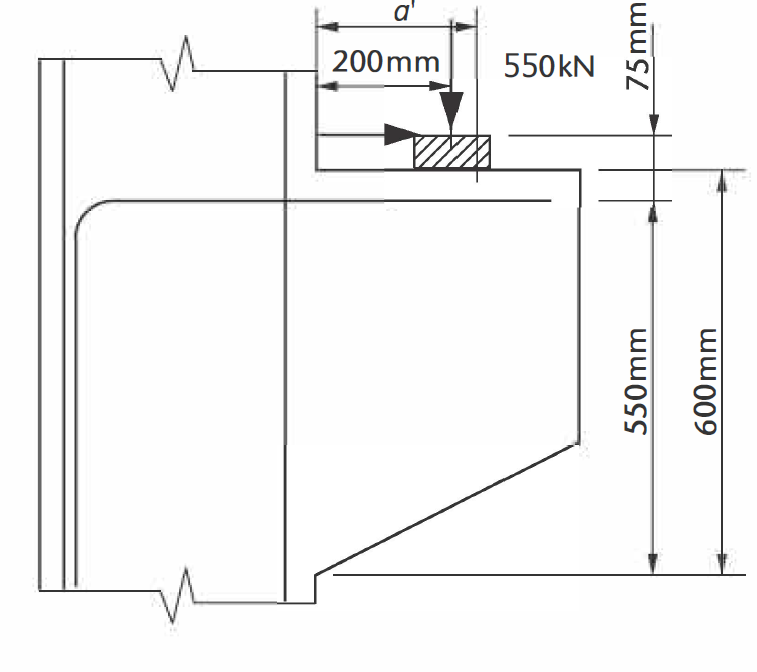
Worked Example
Determine the quantity of reinforcement required for the depicted corbel in Figure 2. This corbel possesses a width of b = 450mm and sustains an ultimate load of FEd = 550kN positioned at a distance ac = 200mm from the column face. The bearing is adaptable and situated a distance aH = 75mm above the tension tie, measuring 450mm by 200mm. The characteristic material strengths are: concrete compressive strength fck = 30N/mm² and yield strength of reinforcement steel fyk = 460N/mm².
Verify Bearing Stress
We must first determine that the actual bearing stress does not exceed the safe bearing stress of the corbel geometry.
Safe Bearing Stress
0.48(1 - f_{ck}/250)_{fck} \\= 0.48(1-25/250)25=10.8MpaActual Bearing Stress
=\frac{550\times10^3}{450\times200} =6.1MpaSince actual bearing stress (6.1Mpa) is less than the safe bearing stress, we can adopt the corbel geometry and proceed to determine the concrete struts.
Determine Concrete Struts
The effective depth of the corbel is taken as d =550mm. And the distance a’ from figure 1 will be given as:
a'=(200+0.2\times75)=215mm
Therefore a’/d:
\frac{a'}{d}=\frac{215}{550} =0.39 f_{cd}=0.34f_{ck}(1-f_{ck}/250)\\=0.34\times25(1-25/250)\\=7.65Mpa\frac{F_{Ed}}{f_{cd}db_w}=\frac{550\times10^3}{7.65\times550\times450} =0.29Hence, from Figure 2 we can determine the value of θ = 59.5o
z=a'tan\theta=215tan59.5\\=365mm (>a_c=200mm)
Main Tension Steel
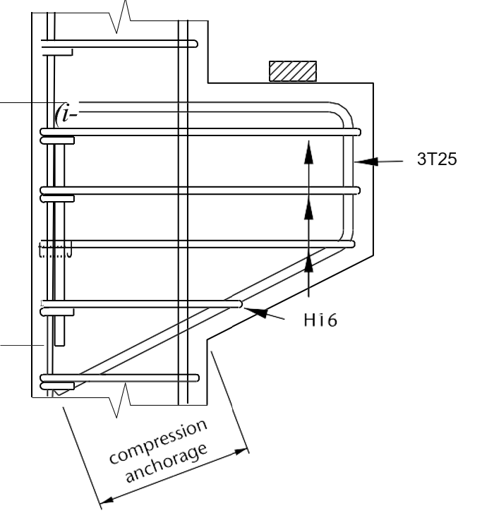
F'_{td} =F_{Ed}(cot\theta+0.2)\\=550(cot59.5+0.2)\\=434kNA_{s,min}=\frac{F'_{td}}{0.87f_{yk}} =\frac{434\times10^3}{0.87\times460} =1084.5mm^2Provide 3T25mm Bars (As_prov =1473mm2)
Horizontal Links
Because ac/hc = 200/600 = 0.33 (< 0.5) closed horizontal links will be provided. The total area of both legs of a link, As,link, is given by:
A_{s,link} > 0.5A_{s,main} = 0.5\times1084.5\\=542.3 mm^2Provide four 3H16 links, each with area As,link = 603mm2.
Design Resume
Figure 4 shows the detailing of the reinforcement in the corbel.
See: Design for Shear using Bent-up Bars
Sources & Citations
- Mosley W. H., Hulse R. and Bungay J.H. (2012) Reinforced Concrete Design to Eurocode 2 (7th ed.) Basingstoke, UK: Palgrave MacMillan