This fourth article in the series on concrete bridges examines the initial parameters that might determine the best layout for a new bridge.
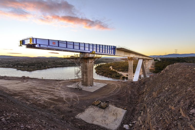
One of the factors that a bridge engineer must think about at the conceptual design phase of any new bridge is the determining the best layout for the bridge. Usually, the client is expected to have described the basic requirements in relation to establishing the best location for the bridge. This choice of location will be governed by the type of crossing that is required (highway, railway or footbridge), and over what sort of obstacles the bridge needs to cross (water, highways, railways or utilities). The alignment of the bridge, and the required loadings that it has to carry, are likely to be determined at this early stage too. Careful thought about the best construction methods must also be accommodated even at this stage, as several perfectly sound methods might be eliminated through an inappropriate early decision. For example, a launched bridge scheme (Figure 1) might be excluded if alignment would be complex. Or, where only one short end of the bridge needs to be widened to carry a slip road, then the costs of the project are likely to be considerably more as the bridge deck will need to be made flexible enough to allow for such a variation. In such instances, it may be much better to re-consider the alignment and road layout in order to produce a bridge that can be made more uniform and repetitive, and thus become more economical.
In simple terms, the deck area and the length of the typical span determine many of the bridge options. Larger schemes (e.g., those with deck areas over 10,000m2) can accommodate several methods (such as precast segmental techniques) that would be inappropriate for smaller deck areas. The range of construction methods for bridges with typical spans between 50m and 100m (such as in-situ or precast balanced cantilevers) can be quite different to those with spans between 20m and 50m (such as in-situ slabs or beams, or precast beams)1.
The availability of sufficient working access and space is another important consideration. It can help to simplify and speed up the construction process. A bridge owner should therefore be made aware of all the available construction methods (such as the need for on-site casting and storage areas), as these issues could easily determine the amount of land that needs to be purchased, or temporarily acquired. This implies that opportunity should be made for involvement from the whole team (owner, designer and contractor) at this early stage, so that decisions are made with a clear understanding of all the issues, with the bridge owner’s priorities being fully understood.
A bridge owner should try to leave as many of the parameters as flexible as possible, such that the designer and contractor can consider all the available construction methods – this strategy will lead to the optimum solution.
Span Requirement
As posited, span requirement is one of the most important parameters that define a bridge layout. Span layouts are often determined by the obstacles that a bridge is required to cross, however, sometimes it is then generally possible to rationalize the spans to generate either a more typical layout throughout, or a more aesthetically pleasing one, or ideally both. Decisions taken at this stage will fundamentally affect all future components of the bridge scheme and it is therefore imperative that they are taken by the most skillful and experienced engineers in the team, who appreciate the impact upon the overall value of the project, to both the owner and society.
In selecting a layout, Pier locations should be chosen to be clear of water wherever possible, both to avoid the need for cofferdams or other marine works, and to reduce the restrictive effects on navigation, wildlife, flood or tidal variations. Columns that are positioned well clear (more than 5.7m) of highways and railways can also be designed without the additional costs of impact forces. The overall substructure layout will affect the best choice of bridge type. The wide range of available foundation and pier options are hugely dependent on precise and particular geology of the bridge location.
The costs and programme for particular substructure options also need to be considered in the overall package of options, which will ultimately allow the most suitable bridge layout to be chosen. In areas of difficult foundations, such as over deep water, the bridge tends to be optimized with longer spans over about 80m (and up to 300m or more) (Figure 2).
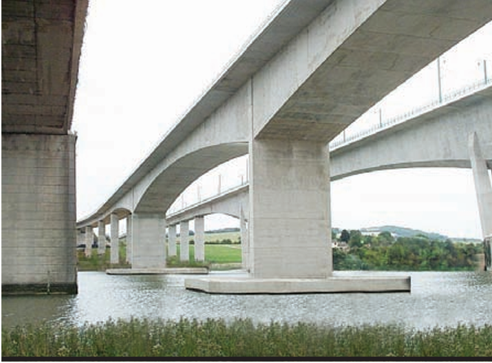
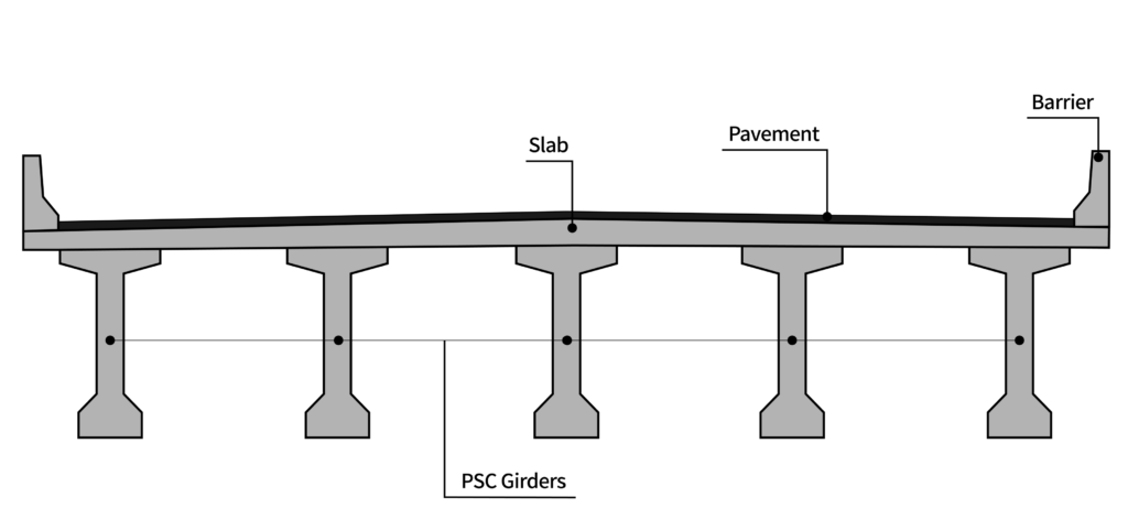
Intermediate spans of 50-80m tend to be used in poorer ground or over shallow water2. In areas of easy foundations, such as over land and good ground, the spans tend to be 20-50m (Figure 3). These shorter 20-50m spans are best progressed as in-situ slabs or twin-ribs, precast beams, in-situ boxes, precast segmental or incrementally launched boxes, whole span precast units or as the modular precast concrete bridge. The intermediate 50-80m spans are best as in-situ, precast segmental or incrementally launched boxes, whole-span precast units or as in-situ balanced cantilever boxes2. The longer spans (over 80m) are best as in-situ or precast balanced cantilever boxes, or as extradosed or cable-stayed schemes2. It is common with long bridges with regular spans, for the span to be chosen by the foundation size and type. For example, where a particular pile cap solution works well with four 1.5m diameter bored piles, or even with a single 2.5m diameter pile, it may be best to select the span to exactly match the capacity of that foundation.

Articulation & Fixity
Concrete which constitutes the majority of bridges is known to expand and contract with temperature changes; it shortens under creep and shrinkage, and will no doubt deflect under applied loads, prestress and temperature gradients. But bridges need to be held safely in all directions at all times, including during construction, when subjected to wind, traffic forces, seismic activity or various impact loads. Hence the need for articulation. The articulation of a bridge is the measures taken to control its overall position while allowing it to move and deflect.
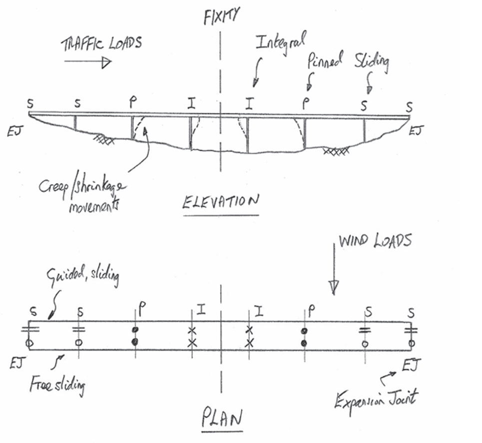
Most bridge decks are generally best fixed transversely at all piers, usually with a guided, sliding bearing that allows longitudinal movement but is rigid transversely. Longitudinally, it is often best to fix the deck upon a central pier, or group of piers – this minimizes the differential friction forces that arise from the group of sliding bearings and equalizes the movements at each end (Figure 4).
Alternatively, a bridge can be fixed at one of the abutments, which does enable all the piers to be kept quite slender. However, this option significantly increases the longitudinal fixing forces (as the fixed bearings have to carry the sum of all the friction forces on all the other bearings) and concentrates them at a location where the vertical reactions are small which then undermines the fixity.
In seismic regions, shock absorbers can be used – these allow normal movements under creep, shrinkage and temperature, but lock up under seismic accelerations, thus spreading the load over more of the substructure. Alternatively, one can isolate the deck from the substructure with the use of elastomeric bearings. The thickness, and hence the shear stiffness, of each bearing can be adjusted such that, in combination with the elasticity of the piers and foundations, the distribution of all the longitudinal forces is under control.
Joints and Bearings
Bridges are generally best formed as continuous structures with no joints, other than at their ends. Thus, when preparing a bridge layout, this should be considered. When the deck is very long, it may be necessary to divide it into several expansion lengths by using intermediate joints. Concrete highway viaducts can often be more than 1km in length, without intermediate joints, with the longest in the UK believed to be 1.75km (Figure 5). This absence of joints also provides a better ride quality and structural performance through the redundancy. As such, the distance between structural expansion joints on highway bridges should be maximised wherever possible. The railway environment, on the contrary is different, as more frequent joints in the structure are often preferred so as to eliminate any rail joints, which can be expensive and need regular maintenance.

Some construction methods are better suited to forming simple spans, such as when standard or bespoke precast beams are used. But even schemes that are built as a series of simple spans can be subsequently joined together to reduce the number of joints – this might be via a structural connection that then makes the whole deck depth continuous, or it might be via a system that makes only the deck slab continuous. This latter option is common, with long viaducts built using whole span precast units where the main structure remains determinate, but the deck slab becomes continuous, allowing a better road surface by eliminating the joints.
For a prestressed concrete bridge, it can be shown that the balance between using either simple or continuous spans is quite close for spans around 25-50m, though continuity generally saves prestress. This better performance of a continuous deck in distributing loads is partly eroded by the secondary effects that arise from continuity, such as differential settlement and temperature. However, the choice of the most appropriate construction method will generally dictate the best solution. For spans over about 50m, concrete bridges should always be continuous.
Thus, elimination of joints should be high on a designer’s list of priorities, when preparing bridge layout. Not just for the aforementioned reasons but as historically they have been the source of many bridge maintenance issues. And Joints also need to be inspected regularly, requiring good access and space beneath the joint for this purpose.
Where joints are necessary, a good layout must aim to reduce the quantity of bearings. This is generally advantageous for improving durability and minimizing maintenance efforts. In regions near longitudinal stability, it is often feasible to eliminate bearings. If the piers are sufficiently flexible, the deck can be seamlessly integrated into the pier, despite the apparent complexity during construction. This integration not only enhances stability during temporary construction phases but also simplifies the structure overall.
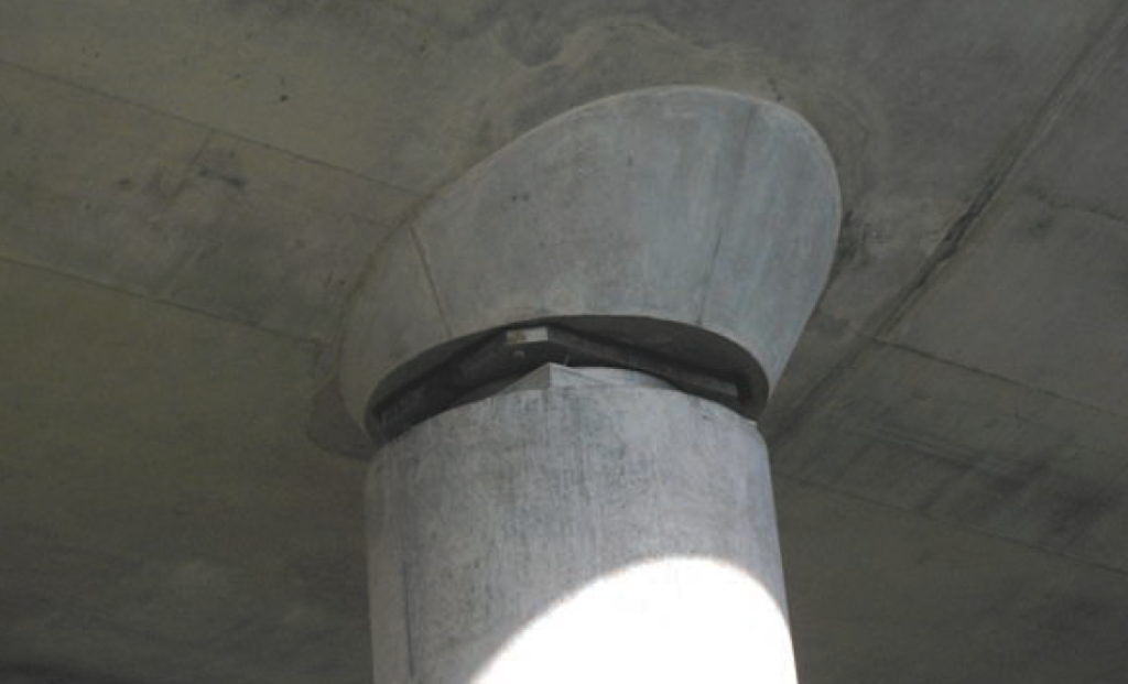
For locations farther from the fixity point, securing the deck with pinned bearings becomes possible. Only when the piers are more than 50-100m away from the fixity point is it essential to incorporate sliding bearings, depending on pier height and flexibility. Among bearing options, pinned bearings are the most cost-effective, involving fewer mechanical components as depicted in Figure 6. In contrast, sliding bearings are inherently more intricate, requiring materials like polytetrafluoroethylene.
Regardless of the chosen bearing type, it is crucial to ensure good access for inspection and maintenance, including providing adequate space and strength for necessary jacking operations to replace the bearings. It’s worth noting that the lifespan of bearings (and joints) is considerably shorter (around 20-30 years) compared to the overall lifespan of a bridge.
See: Design of Specialist Concrete Bridges
Conclusions
Prioritizing the selection of an optimal bridge layout in the early stages helps bridge owners secure maximum benefits. In a future article, the strategies that may empower designers to pinpoint schemes delivering unparalleled advantages, ensuring informed decisions and long-term success in concrete bridges will be presented. Stay tuned.
Sources & Citation
- Concrete Bridge Development Group (2014) ‘Concrete Bridge Design & Construction Series No. 6: construction bridge construction method -Precast’, The structural engineer, 92(7).
- Concrete Bridge Development Group (2014) ‘Concrete Bridge Design & Construction Series No. 6: construction bridge layouts’, The structural engineer, 94(2).