This article provides insights and useful guidance on assessing thermal actions on building structures based on Eurocode 1 (part 5)
Thermal actions on buildings encompass a range of phenomena resulting from variations in temperature. These effects can manifest in structural elements through expansion, contraction, and differential movement, potentially leading to stress buildup, deformation, and even structural failure over time. Additionally, thermal actions can influence the performance of building materials, affecting their mechanical properties and long-term durability. Beyond structural considerations, thermal effects also impact energy consumption and indoor comfort, as buildings respond to external thermal stimuli through heating, cooling, and ventilation systems. Thus, comprehensively understanding and effectively managing thermal actions is crucial for ensuring the safety, functionality, and sustainability of buildings across diverse environmental conditions.
Eurocode 1 Part 1-5, a pivotal publication in 2003 within the Eurocodes series, marked the inaugural codified guidance specifically addressing thermal effects on buildings in Europe, although prior guidance existed for assessing such effects on bridges. Although concise at only three pages, Section 5 furnishes essential guidance for building structures. Its focus lies on advising on temperature values utilization and their amalgamation, assuming designers will utilize calculated temperature changes to ascertain potential movements and subsequent implications for buildings, such as necessitating movement joints or influencing material strains due to restraint.
The code defines the uniform temperature component as:
\Delta T_u=T-T_o
The definition is slightly misleading as the delta is used as the symbol to represent a change in value, as is normal convention. ΔTu should therefore be considered to be the change in temperature since construction.
Where:
- T is the average temperature of a structural element, and this can vary depending on the season, climatic effects and internal temperatures.
- T0 is the initial temperature of the element, i.e. at the time of construction, or when the element is restrained by other elements.
The key information provided in section 5 is in Tables 5.1 to 5.3 of BS EN 1991-5
Table 5.1 provides guidance on the internal building temperatures in the summer or winter months. This is very generic and project-specific values would be more appropriate, e.g. a hospital will have a higher internal design temperature than a sports hall. It would also appear to reflect typical European values and should be adjusted for other situations. This could be where air conditioning is typically set with a lower temperature than these values, or situations where buildings are not cooled.
Tables 5.2 and 5.3 of the above referenced codes also provide values for the external surfaces of buildings for above- and below-ground conditions respectively. It is important to note the values are only suitable for regions between latitudes 45°N and 55°N. This is quite a restrictive range; Milan is at 45°N and the English/Scottish border passes through 55°N2. So, anywhere south of northern Italy and north of England is outside the scope of the guidance.
National maps showing characteristic values for maximum and minimum shade temperature are given in the appropriate National Annex. Finally, Annex C provides values of the co-efficient of thermal expansion. The value for concrete is given as 10 × 10-6, whereas in Eurocode 2 it is given as 12 x 10-6, so it pays to be aware that for some materials the values can change.
Concrete, masonry and timber are examples of materials for which the value can vary significantly. Concrete temperature movements are significantly affected by the aggregate used. Timber temperature movements vary along or across the grain, according to the species and even according to the moisture content. The best advice is to research an appropriate value for the particular material being used, especially when the thermal effects are critical to the design. There is more detail for masonry later in this article.
Estimating Movement in Practice
A worked example is presented for the concrete roof of a 50m long building, which happens to be in the UK. This is informative, as the advice in the IStructE manual for steelwork2 is to allow for 15-25mm of movement and to have movement joints at 50m spacing. The IStructE manual for concrete structures3 also recommends movement joints at 50m spacing and each joint should be 25mm wide. Note that this is not the same as allowing for a movement of 25mm, since any material filling the joint will not allow for the full movement.
Worked Example
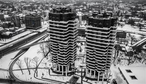
Determine the characteristic increase and/or reduction for the longest building dimension for the roof plan shown, located in Leicester, UK. The roof is a concrete fat slab 250mm thick, with a dark-coloured surface. Assume the temperature during construction will be 10°C.
Obtain from tables in BS EN 1991-1-5:
- Table 5.1: Inside temp. – summer (T1): 20°C
- Table 5.1: Inside temp. – winter (T2): 25°C
- Table 5.2: Solar radiation effect (T5): 42°C
Obtain from UK National Annex:
- Figure NA.1: Min. shade temp (Tmin): −17°C
- Figure NA.2: Max. shade temp (Tmax): 34°C
Assuming that the temperature at the time of casting is 10°C
\Delta T_{u,max} = (T_{out}+T_{1})/2-T_o \\=(76+20)/2-10 =38^oC\Delta T_{u,min} = (T_{out}+T_{1})/2-T_o \\=(-17+25)/2-10 =-6^oCAssuming the coefficient of expansion and contraction of concrete is 12 x 10-6, we can determine the expansion and contraction of the frame as follows:
Expansion
50000\times12\times10^{-6}\times38 =22.8mmContraction
50000\times12\times10^{-6}\times-6=-3.6mmThe example suggests that the movement will be 22.8mm, and we can conclude from this that the general advice in the manuals is appropriate, provided that only thermal effects are acting.
Figure 1 shows how making changes to various input data for different design scenarios has an effect on movement. (The changes are highlighted in bold text.)
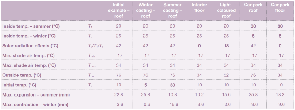
The initial temperature was taken as 10°C, but changing the initial temperature has a noticeable effect. If the temperature is 5°C (the usual recommended minimum temperature for casting concrete) the potential movement increases to 25.8mm. Conversely, casting concrete at 30°C (the usual recommended maximum) significantly reduces the expansion, but significantly increases the contraction.
The example is for a roof, where one face is exposed to external temperatures. If the element is an internal floor, the movement is significantly reduced. At first sight, this would suggest it is less of a problem; however, it should be considered that if this is the floor below the roof, then there could be differential movement of more than 15mm between this floor and the roof. This could induce moments in the columns which might need to be considered in the design.
This could be mitigated if the surface of the roof is much lighter in colour, so the differential movement would be less than 5mm. Alternatively, if the structure is within the insulation, there would be significantly less movement.
Finally, it is worth noting that for a car park with a dark-coloured surface, the movement could be nearly 29mm.
Having determined how much movement is likely to occur, it will be necessary to consider how to deal with the potential movement. Movement joints are an option, but they introduce costs and future maintenance issues.
The alternative is to consider what stresses or forces are applied to the structural elements if the building is not free to move. If that approach is taken, then the temperature effects may occur at the same time as other loads. In some cases, they may be beneficial, but they can also be adverse and therefore should be added to the other actions.
Construction Temperature
As previously mentioned, the selection of the T0 value significantly influences the extent of movement. Designers typically cannot predict the exact construction day temperatures; thus, a prudent approach involves evaluating effects for both cold and hot conditions. In the UK, customary practice for concrete-framed buildings, based on NSCS4, entails specifying minimum and maximum temperatures of 5°C and 30°C respectively. For materials where thermal effects induce substantial movement, designers might contemplate implementing analogous constraints. Given the absence of constraints in NSSS5 and NSTS6, it’s advisable to clearly communicate any restrictions to the contractor.
Restraints
When assessing the significance of calculated thermal movement, considering the effect of restraint is paramount. Unrestricted movement results in no strain within a member, while restraint occurs when movement is impeded. Restraint sources vary, ranging from soil in ground-bearing slabs or foundations to the building frame in aluminum cladding systems or rigid core walls within a building frame.
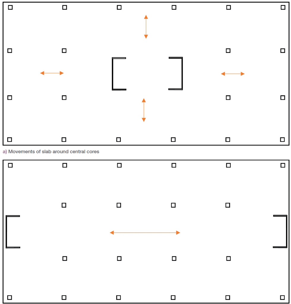
Figure 2 illustrates how the positioning of core walls can impact strain within a slab differently. In Fig. 1a, centrally located cores, being relatively stiff, lead to most movement directed toward and away from the cores. For instance, in a roof slab scenario, an anticipated 11mm lengthwise expansion from the core may indicate no further checks are necessary.
Conversely, in Fig. 1b, where movement primarily occurs between two core walls, a potential 15.6mm contraction between the cores could result from casting the same roof slab on a hot day.
Given the cores’ restraining effect, the slab strain would be significant, necessitating consideration due to the concrete’s characteristic tensile strength of 3.3MPa, potentially leading to cracking and thus requiring adjustments in the concrete slab design or construction sequence.
Movement Between Cladding & Frames
While the example addressed building-wide movement, issues can arise on a smaller scale, particularly regarding movement between the frame and the cladding system.
Material variations in the coefficient of thermal expansion can be substantial, with aluminum reaching up to 24 and PVC ranging from 54 to 110, resulting in potentially significant differential movement2.
Additionally, the supporting structure often resides in an internal environment, whereas the cladding faces external conditions, experiencing a full spectrum of temperatures. Thus, careful consideration must be given to how the cladding is affixed to the frame, ensuring that fixings allow for movement between the elements where appropriate.
Although thermal movement alone may not greatly affect small panels, when combined with other movements, such as beam deflection, they could become significant. Hence, it’s vital to account for all effects when assessing connections between the cladding and the supporting frame.
Movement in Masonry
Masonry encompasses both brickwork and blockwork, each with distinct coefficients of thermal expansion. Blockwork can further vary between concrete and aerated concrete, with constituent materials affecting expansion values. Whether loadbearing or used as cladding, potential movements must be considered for masonry in both applications.
Two notable considerations arise with masonry. Firstly, in cavity walls, where two leaves often employ different materials, their varying rates of movement must be accounted for. Additionally, brickwork’s volume fluctuates with changes in moisture content, prompting the recommendation for movement joints typically spaced at 9m to 12m intervals.

Building layouts frequently incorporate facade setbacks, a factor often overlooked yet prone to potential failures due to movement. Introducing a short return within an extended wall length can result in significant longitudinal movement between the sections, generating substantial shear forces across the return (see Figure 3). Masonry’s susceptibility, owing to its poor tensile strength, underscores the need for appropriate measures such as incorporating movement joints or reinforcing bed joints in such scenarios.
Guidance on Car Park Design
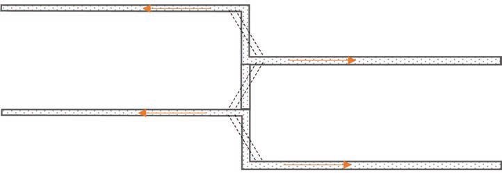
Defects may manifest in multistorey car parks when designers overlook the greater thermal movements compared to insulated buildings. Exposed to the elements, car park structures experience thermal movements likely double those of typical buildings, as illustrated in Table 1. Consequently, the need for movement joints arises at half the standard spacing, approximately 25m apart. However, additional considerations arise, particularly concerning movement between floors, which can impose moments on the columns. While acknowledging that movements on the top deck exceed those on lower decks, in a split-level car park (refer to Figure 4), such movements might affect shorter column lengths.
Depending on construction form, movement at bearings warrants consideration, especially where beams or slabs span 16m—a span commonly observed in car parks and exceeding typical building structures. The exposed nature of car parks, coupled with various sources of movement, can result in significant movements known to cause notable defects if overlooked during the design phase.
Further Guidance
BS EN 1991-1-5 mandates the consideration of thermal actions in building design when there’s a risk of exceeding ultimate or serviceability limit states due to thermal movement or stresses. However, it provides no specific guidance on when thermal movement should be treated as either a serviceability or ultimate limit state, though it’s generally regarded as a serviceability concern, but it can escalate to an ultimate state issue.
The partial collapse of a new terminal building at Charles de Gaulle Airport in Paris in 2004 was attributed to thermal movement, illustrating an ultimate limit state failure due to thermal effects. Serviceability failures, however, can be equally significant—an example being the spalling of bearings in a Bournemouth, UK car park in 2005, resulting in damage to cars and ultimately necessitating the car park’s reconstruction.
As a general advice, a proficient structural engineer should always view thermal effects on a building’s primary structure as a fundamental aspect of its design. Thus, assessing the significance of movement, and identifying potential failure mechanisms is very important. Disregarding thermal movements can lead to critical consequences costly as can be seen by the above-referenced structural failures.
Also See: A Background to Extreme Loading Conditions
Sources & Citations
- British Standards Institution (2004) BS EN 1991-1-5:2003 Eurocode 1. Actions on structures. General actions. Thermal actions, London: BS
- Institution of Structural Engineers (2023) Thermal Effects on Building Structures. Technical Guidance Notes (Level 3-Note 4).