This article provides guidance and recommendations on detailing of concrete slabs based on Eurocode 2
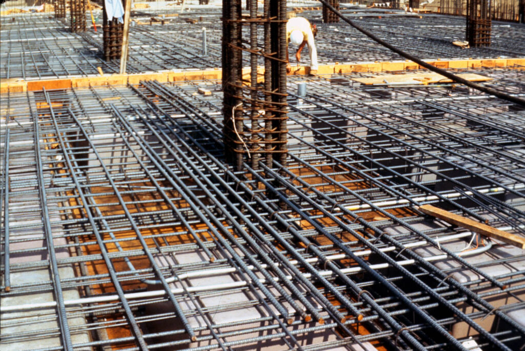
The concrete slabs is one of the most basic structural elements in structures. They can be designed to assume different forms, either as solid slab, flat slab voided slab or even post-tensioned slab. Each of these forms all have their key features, advantages and disadvantages that make them desirable in specific circumstances. However, for any of them, their integrity and longevity rest not only on the quality of the design but also on meticulous detailing. Detailing a concrete slab is the process of translating the design into working drawings that can be used for implementation. Efficient detailing of a concrete slab is paramount properly to ensure that they meet structural requirements while being constructible.
Eurocode 2 offers a comprehensive guideline for the design and detailing of various types of slabs. Eurocode 2 sets forth meticulous standards that encompass every aspect of concrete slab design and detailing, emphasizing the critical elements necessary for their structural integrity and durability. These guidelines, enshrined within Eurocode 2, covers a spectrum of considerations, ranging from the selection of suitable concrete grades to the specification of nominal cover and reinforcement spacing.
This piece outlines the process of detailing a concrete slab, covering aspects such as geometry, concrete cover, minimum and maximum longitudinal reinforcement areas, and the sizing and spacing of longitudinal and transverse bars.
Detailing Rules
The information provided pertains to:
- Single and two-way orthogonal slabs
- Cantilever slabs
- Orthogonal flat slabs
- Trough and coffered slabs
Slabs with irregular shapes can often be detailed using the same principles. However, designing for six or more layers of reinforcement may be necessary, and this should be accounted for in the design process.
For ribbed and coffered slabs, the ribs should be spaced at centers not exceeding 1.5 meters, and their depth, excluding any topping, should not exceed four times their top width. Otherwise, they should be designed and detailed as beams.
Ground slabs are not addressed in this article, a separate article on the design and detailing of ground bearing slabs have been presented in the past (See: Design and Detailing of Ground Bearing Slabs) for more details.
Concrete Grade
The concrete grade typically recommended for reinforced concrete slabs is 30/37 MPa (cylinder strength/cube strength), with an aggregate size not exceeding 20mm. However, lower concrete grades such as C20/25 and C25/30 can also be used.
Nominal Cover (Clause 4.4 of BS EN 1992-1-1)
Solid slabs
- For indoor applications (Concrete within structures with low air moisture, XC1): (15mm or bar diameter) + Δcdev or the greater value.
- For outdoor applications Corrosion influenced by carbonation, XC3) (35mm or + Δcdev)
Ribbed slabs
The above rule for solid slab is also valid for ribbed slabs but in addition, consideration should be given to providing supplementary reinforcement for fire ratings exceeding 2 hours.
Minimum reinforcement area (EC2, Clauses 9.3.1.1, 9.3.1.2, and 9.2.1.1)
The minimum reinforcement area refers to the minimum amount of reinforcement and bar size that should be provided in a concrete slab. The rules as it applies to solid slabs, ribbed slabs and cantilever slabs are outlined below.
Solid slabs
Tension reinforcement.
The minimum area of tension reinforcement (As,min) is calculated using the formula:
A_{s,min}=0.26b_td\frac{f_{ctm}}{f_{yk}} \ge0.0013b_tdwhere:
bt represents the mean width of the tension zone; d denotes the effective depth, fctm is obtained from Table 3.2 of EC2, and fyk represents the characteristic yield strength.
For concrete Grade 30/37 and fyk = 500 MPa, As,min equals 0.0015 bt d.
This calculation also applies to nominal reinforcement.
Minimum bottom reinforcement in the direction of the span: Should be 40% of the maximum required reinforcement.
Minimum top reinforcement at support points (e.g., where partial fixity exists): Should be 25% of the maximum required reinforcement in the span, but not less than As,min. This percentage may be reduced to 15% for an end support.
Secondary transverse reinforcement: Should be 20% of the main reinforcement, except in cases where there is no transverse bending (e.g., near continuous wall supports).
Preferred minimum diameter: 10mm.
Cantilever Slabs
In addition to the rule for solid slab above, exposed cantilevers where shrinkage and temperature notably impact deflection, the bottom reinforcement area in the span’s direction should correspond to approximately 50% of the top reinforcement.
Ribbed Slabs
- The minimum bar diameter within ribs: 16mm.
- The minimum reinforcement in the flange is as required for single-way slabs.
- When utilizing fabric reinforcement, the spacing between wires should not exceed half the rib
Bar Spacing (EC2, Clauses 8.2 and 9.3.1.1)
Minimum spacing of bars
- Recommended minimum spacing of reinforcing bars: 75mm (100mm for overlaps).
Maximum spacing of bars
- Main bars: 3h up to 400mm (in areas with concentrated loads, 2h up to 250mm).
- Secondary bars: 3.5h up to 450mm (in areas with concentrated loads, 3h up to 400mm).
Anchorage and Lapping of Bars (EC2, Clauses 8.4 and 8.7)
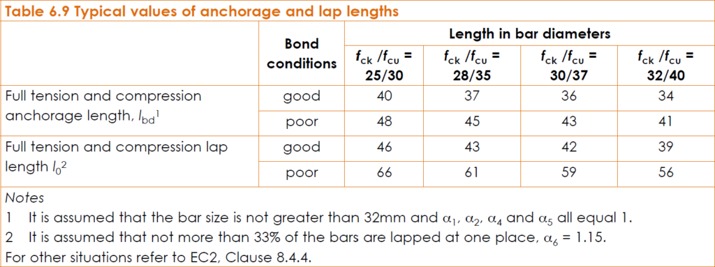
Figure 1 provides typical anchorage and lap lengths for ‘good’ and ‘poor’ bond conditions for high yield and 500 Grade steel.
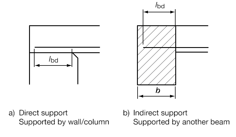
For ends positioned on ‘direct supports’ (refer to Figure 2), the anchorage length extending beyond the face of the support can be reduced to d, but not less than the larger of 0.3 lb,rqd, 10b, or 100mm. In cases of abnormally high loading or where point loads are near the support, EC2, Sections 8 and 9 should be consulted.
Lap lengths specified (for nominal bars, etc.) should be no less than 15 times the bar size or 200mm, whichever is greater. The arrangement of lapped bars should adhere to Figure 3.

Anchorage of Bottom Reinforcement at End Supports (EC2, Clauses 8.4.4 and 9.2.1.4)
The bottom reinforcement area supplied at supports with minimal or no assumed end fixity in design should be a minimum of 0.25 times that provided in the span.
Simplified Guidelines for Reinforcement Curtailment:
When providing only the minimum percentage of reinforcement, curtailment should be avoided.
For situations where adjacent spans are roughly equal (within 15%) and loading is uniformly distributed, simplified curtailment rules can be applied without the need for bending moment diagrams.
In other cases, the curtailment of main longitudinal reinforcement should be determined based on the bending/shear moment diagram. The lever arm (al) may be considered as the effective depth (d) for slabs without shear reinforcement.
If analysis is conducted for the single load case where all spans are loaded and no shear reinforcement is needed (refer to 5.1.3 (1)P of the UK National Annex of EC2), a simplified method for curtailment of bars can be employed.
Top Bars
Determine the appropriate bar size and spacing for the maximum moment, ensuring that twice the spacing for the half moment value does not exceed the allowable limit.
Compute the lengths for alternating bars (a + b) and (c + d). If the disparity is less than 500mm, standardize the length of all bars to the greater value.
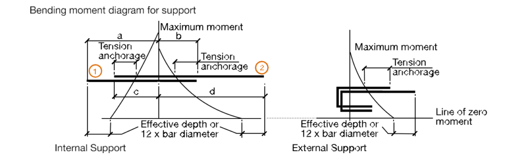
Arrange the bars in an alternating staggered pattern, with points (1) and (2) in the diagram serving as the outer boundaries. Bars over end supports should also be staggered alternately and typically provided as two sets of U-bars (Figure 4).
Although not mandatory, it is advisable to incorporate a continuous top mesh over the central sections of slabs and flat slabs for several reasons:
- Control of shrinkage cracking
- Reduction of deflections
- Prevention of trip hazards during and after concrete placement. A mesh of at least A252 grade is recommended as a minimum requirement.
Bottom bars
Determine the appropriate bar size and spacing for the maximum moment, ensuring that twice the spacing for the half moment value does not exceed the allowable limit (Figure 5).
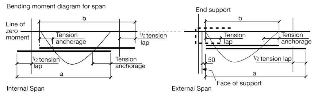
For internal bays, the length of all bars should be the greater of ‘a’ and ‘b’. Alternate bars should be staggered accordingly.
For end bays, the length of alternate bars should be ‘a’ and ‘b’
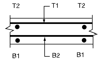
Notation for the arrangement of reinforcement layers
Reinforcement is arranged in layers, beginning from the bottom of the slab and moving upwards, with bar marks ideally following a sequential numbering pattern. The notation is as follows:
- Abbreviation for the top outer layer: T1
- Abbreviation for the top second layer: T2
- Abbreviation for the bottom second layer: B2
- Abbreviation for the bottom outer layer: B1
Include the sketch and notation on each drawing (Figure 6).
Detailing Information
Finally in presenting the detailing of the slab reinforcement, it should be organized as follows:
Layout and Section Drawings: These should encompass detailed representations of elements like holes and upstands.
Concrete Specifications: This includes the grade and aggregate size, with standard values e.g. 30/37 MPa for concrete grade and 20mm for aggregate size.
Reinforcement Cover: Specify the nominal cover to reinforcement, considering design factors such as fire or durability. Standard values are 20mm for internal conditions and 40mm for external conditions.
Main Reinforcement Bar Details: This section should cover the diameter, pitch, and location of bars (e.g., T1, T2, B1, B2, etc.), along with the type and bond characteristics (standard: H) of reinforcement, and fixing dimensions for positioning bar runs and ends.
Special Moment Bars: Provide details of any special moment bars connecting slabs to walls or columns.
Cut-off Rules: Detail any deviations from the standard cut-off rules shown in the model details.
Fabric Requirements: Include the fabric required, particularly for coffered slabs, detailing the topping and solid section reinforcements around columns. Ensure sufficient details to accommodate reinforcement fitting and laps in the fabric. Guidance should be provided for the additional area required for laps; otherwise, 22% will be assumed for 300mm laps.
Insertions Details: Specify any insertions such as conduit, cable ducting, or cladding fixings that may affect the placement of reinforcement.
Also See: A Guide to the Detailing of Foundations
Sources & Citations
- The Institution of Structural Engineers (2006) Standard Methods of Detailing Structural Concrete- A manual for best practice (Third Edition) London: The Institution of Structural Engineers.